Table of Contents
Advertisement
Quick Links
Advertisement
Table of Contents

Related Manuals for ViTiny UM08-CSZ064


Summary of Contents for ViTiny UM08-CSZ064
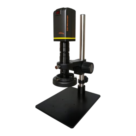
- Page 1 UM08-CSZ064 User’s Guide Version 1.1A...
-
Page 2: Table Of Contents
Contents Product Introduction ......2 Packing Contents ......2 CSZ064 Lens Assembling ..... 2 IR Remote controller....5 Microscope menu functions ..8 Microscope introduction: ..22 Microscope Focus ...... 27 Microscope accessory....29 Printed Notice ........29 Maintenance ......29 Product Specification .... -
Page 3: Product Introduction
Product Introduction 1.1 Packing Contents The box contains 1 camera and 9 accessories. Item Q’ty Item Q’ty Microscope Camera White Balance Card HDMI Cable IR Remote Control Power adaptor User’s Guide S114 Stand CSZ064 Lens Stand assemble guide LED Ring Light GN03 1.2 CSZ064 Lens Assembling 1.2.1 Fix microscope Each CSZ064 lens has reach its parfocal distance when goods ship... - Page 4 ○ ○ 1.2.2 Start to use microscope Connect the HDMI cable and adaptor within the box ○ ○ to HDMI monitor and power. See below:...
- Page 5 ○ ○ 1.2.3 Power On/Off Press Power to turn on microscope. Choose HDMI mode or Auto on HDMI monitor to output image.
-
Page 6: Ir Remote Controller
1.3 IR Remote controller The microscope operation and functions is controlled by the IR remote controller. (1) Power Turn on/off. : :No Function. (2) HDMI :No Function. (3) PC CAM :No Function. (4) Snapshot Only when connect to optional accessory Image Capture Box IMB05 for snapshot. - Page 7 :Zooms in; speed increases when held. (7-1) Zoom in :Zooms out; speed increases when held. (7-2) Zoom out (8) Autofocus: Does not suggest to use this function in CSZ064 model. Whenever active the AF function, sensor position will change. This might cause the sensor position not at the end so image will not clear in every stage when manual adjust.
- Page 8 :Choose the next item (12) Down :Choose the next value (13) Left :Choose the last value (14) Right :No Function (15) Video Ratio :Status bar show [FL] for free lens. By switching (16) Status Bar the Status bar, it will show OZ (sensor position), and EV (Exposure).
-
Page 9: Microscope Menu Functions
(18) Image Freeze : ON/Off to freeze or unfreeze the image. (19) Sharpness : On/Off to set sharpness at Minimum and Maximum level. 1.4 Microscope menu functions There are 8 functions in menu, press Up and Down choose item, Left and Right to turn on/off or adjust parameter. - Page 10 1.4.1 EXPOSURE To set exposure time, see below: (1) Shutter: Digitally control amount of light, the amount is smaller the image is darker and the frame rate is also slower. (2) AGC (Auto Gain Control): auto control the brightness based on setting when light is not enough.
- Page 11 (6) DEFOG:De-Fog. When observing under strong light or special environment, use Defog function to see clear image. Below fig for De-Fog setting. (6-1) POS/SIZE:Adjust de-fog position and area. (6-2) GRADATION:To set gradation levels near the edge of defog area. (6-3) DEFAULT:Return to default setting. (6-4) RETURN: Return to last page.
- Page 12 (2-1) GAIN: Set WDR gain level to raise up brightness of darker image. (2-2) WDR OFFSET:Wide Dynamic Range OFFSET. (2-3) RETURN: Return to last page. (3) BLC (Back Light Compensation) To adjust brightness for darker image in back light environment. (3-1) GAIN: To adjust brightness level.
- Page 13 (4) HSBLC (High Suppress Back Light Compensation) To identify the over luminance area by backlight, and proceed masking the area. (4-1) SELECT: Select the areas which needs to be adjusted. 4 areas are selectable. (4-2) DISPLAY: Display the selected area. (4-3) LEVEL: Set value to judge if the image is too bright.
- Page 14 (4-8) DEFAULT: Return to factory default setting. (4-9) RETURN: Return to last page. 1.4.3 MANUAL WB Calibrate the white balance. (1) AWB: Auto white balance. (2) ATW: Auto tracing white area and calibration. (3) AWC->SET: Semi-auto white balance. Use to track the white color from current image.
- Page 15 (1) 2D NR:ON/OFF, Edge Preserving 2D NR. (2) 3D NR:ON/OFF, Motion Adaptive 3D NR. See below: (3-1) SMART NR: Distinguish the moving object not moving noise, and auto close the “3D NR”. (3-1-1) The sensitivity to detect the moving SMART NR: object.
- Page 16 (3-5) Return: Return to last page. (3) Return: Return to last page. 1.4.5 SPECIAL Set special functions: (1) D-EFFECT: There are few more functions in D-EFFECT, but (1-3), (1-4) and (1-6) function can only turn on one item at one time. Press Left or right to turn on or off.
- Page 17 (1-1) FREEZE: Turn ON/OFF to freeze image. If Freeze function is turn on, the (1-2) Mirror function can not be used at the same time (1-2) MIRROR: Image rotatory. (Horizontal or Vertical) (1-3) D-ZOOM: Digitally enlarge the chose area. Digital zoom selection can from 1-62 times.
- Page 18 (1-3-2) D-Zoom: Set digital zoom times. (1-3-3) PAN&TILT: To set the enlarge position. (1-3-4) DEFAULT: Return to default setting. (1-3-5) RETURN: Return to last page. (1-4) SMART D-ZOOM: Assign 1 or 2 areas to enlarge the image from 1-62 times whenever detected the object moves.
- Page 19 (1-4-1) SELECT: Choose the enlarge area, totally 2 areas. (1-4-2) DISPLAY: Display enlargement frame. Position and area can be set in (1-4-1) (1-4-3) SENSITIVITY: The sensitivity to detect whenever object moves. The lower value gets the higher sensitivity. (1-4-4) PIP: No Function. (1-4-5) D-Zoom: Set magnification times.
- Page 20 (1-5) NEG. IMAGE: Turn On/Off Negative image. (1-6) DIS: Digital Image Stabilization function. (1-7) RETURN: Return to last page. (2) MOTION: Detect the moving object, see below setting. (2-1) SELECT: Select the areas which needs to be detected. 4 areas are selectable. (2-2) DISPLAY: Display the selected area.
- Page 21 (3) LANGUAGES: 16 languages are selectable. (4) DEFFECT: Dead Pixel compensation. (4-1) LIVE DPC: Dead Pixel Correction. Correct the live dead pixel during preview. (4-2-1) LEVEL: Set the threshold value to judge if it needs RETURN: Return to last page. (4-2) STATIC DPC: Static Dead Pixel Correction, scan and find the dead pixel then save the position for correction.
- Page 22 (4-2-1) START: Start to do Static Dead Pixel correction. (4-2-2) LEVEL: Set the threshold value to judge if it needs to be corrected. (4-2-3) SENS-UP: Raise up the sensor’s sensitivity to compensate the dead pixel. (4-2-4) AGC: Auto Gain Control. When light is not enough, AGC will follow the threshold setting to compensate the dead pixel.
-
Page 23: Microscope Introduction
(2) LSC:Lens Shading Correction. Use Lens shading correction to average the luminance of image. 1.4.7 RESET Return to factory default setting. Press Left/right button to choose “CHANGE” to return default. 1.4.8 RETURN Exit from menu. 1.5 Microscope introduction: 1.5.1 IR Remote Area/Indicator and ○... - Page 24 ○ ○ ○ (1) IR remote control aiming area ○ The indicator will blink whenever buttons are pressed. If the indicator did not blink means the signal was not delivered and please repress again (2) HDMI indicator○ When lit up, the microscope is in HDMI :...
- Page 25 1.5.2 Power/USB/HDMI port Caution: Please hold the cable when remove from microscope and do not disassemble cables forcefully. ○ ○ ○ (1) HDMI ○ The HDMI port is used to connect the microscope to : a screen. When the device is in HDMI mode, connect the microscope to the screen using the HDMI cable from the box.
- Page 26 1.5.3 Ring Adaptor Assembling Assemble the stand first. Insert CSZ064 lens into Ring Adaptor ○ and screw tight with Hex Key. Insert lens with Ring adaptor into Universal Adaptor then screw tight ○ , the lens face front center position. ○...
- Page 27 1.5.4 Illuminance (1) LED Ring Light ○ : Insert LED Ring Light from bottom and use hex key to screw tight. Connect LED Ring Light power then turn ON/OFF. ○...
-
Page 28: Microscope Focus
1.6 Microscope Focus Move the CSZ064 lens upward, leave 82mm from the object; press Zoom out button, move the sensor to end position. Turn the optical zoom to 4x ○ , move up and down the universal gear box ○ to find the clear image. - Page 29 ○ ○ 1.6.1 Magnification chart The below chart measured base on UM08-CSZ064 model on 24” screen with working distance 82mm, and optical focusing from 0.6x-4x. The chart is only a reference data. For different monitor size, please measure again. CSZ064 Zoom lens working distance: 82mm (3.2”) CSZ064 Lens magnification on 24”...
-
Page 30: Microscope Accessory
Working Distance (mm) Field of View(mm) 18.3 10.9 Magnification (X) 142x 185x 1.7 Microscope accessory 1.7.1 White balance card The white side is used to calibrate the white balance. If the object is tiny, place it onto the white balance card and move the card instead of the object. -
Page 31: Product Specification
2.1.3 Avoid dropping: the device may malfunction if it encounters strong collision, vibration, or distortion. 2.1.4 Turn the microscope off before cutting off the power supply : do not forced cut off the power supply. 2.1.5 Do not face the lens against strong light or sunshine for extended periods of time: Strong light rays may degrade sensitive elements and generate white stains on images. - Page 32 (Output : DC 5.0V/2.0A Input : AC 100-240V Power supplier 50/60Hz) Power 0.225A(Max) Consumption (A/C) Size 280(L)×66(W)×68(T) mm Weight Host weight around 710 grams Temperature -5℃ ~ 50℃; Humidity-lower than Operation environment 85% (No Condensation) For any changes, please visit http://www.vitiny.com...
- Page 33 Please remove the power supply from the microscope when not in use. Do not disassemble the machine for inspection. For any problems occurring in the machine itself, please power off the device and contact us through e-mail: mltc@vitiny.com...
- Page 34 Service fees (including transportation fees) of product inspection. Repair fees. Fees of replaced parts ViTiny Service Center Tel: 07-657-9551 Fax: 07-657-9561 Address: 10 F., No.1, Section 1, Syuecheng Road, Dashu District, Kaohsiung City 840, Taiwan (R.O.C.) Website: http://www.vitiny.com...
- Page 35 ViTiny UM08-CSZ064 Warranty Product Model no S/L nos. Purchase DD/MM/YYYY date Purchaser Tel no: Address Email Distributor Seal for Confirmation ( Stamp is necessary for validation of the Warranty ) ※Distributor’s seal shall include name of the shop, telephone and address※...
- Page 36 HTTP://WWW.VITINY.COM © MicroLinks Technology Corp. All rights reserved.
Need help?
Do you have a question about the UM08-CSZ064 and is the answer not in the manual?
Questions and answers