Table of Contents
Advertisement
Advertisement
Table of Contents

Related Manuals for thomann The t.mix 20.12


Summary of Contents for thomann The t.mix 20.12
- Page 1 20.12 mixer user manual...
- Page 2 Musikhaus Thomann Thomann GmbH Hans-Thomann-Straße 1 96138 Burgebrach Germany Telephone: +49 (0) 9546 9223-0 E-mail: info@thomann.de Internet: www.thomann.de 07.09.2018, ID: 433540...
-
Page 3: Table Of Contents
Table of contents Table of contents General notes..........................4 1.1 Further information......................4 1.2 Notational conventions....................4 1.3 Symbols and signal words................... 5 Safety instructions......................... 6 Features............................8 Installation..........................9 Connections and controls....................10 Operating..........................16 6.1 Main menu........................16 6.2 Parametric Equalizer.................... -
Page 4: General Notes
Our products are subject to a process of continuous development. Thus, they are subject to change. 1.1 Further information On our website (www.thomann.de) you will find lots of further information and details on the following points: Download This manual is also available as PDF file for you to download. -
Page 5: Symbols And Signal Words
General notes 1.3 Symbols and signal words In this section you will find an overview of the meaning of symbols and signal words that are used in this manual. Signal word Meaning DANGER! This combination of symbol and signal word indicates an immediate dangerous situation that will result in death or serious injury if it is not avoided. -
Page 6: Safety Instructions
Safety instructions Safety instructions Intended use This device is intended to be used for amplification, mixing and playback of signals from musical instruments and microphones. Use the device only as described in this user manual. Any other use or use under other operating conditions is considered to be improper and may result in personal injury or property damage. - Page 7 Safety instructions NOTICE! Operating conditions This device has been designed for indoor use only. To prevent damage, never expose the device to any liquid or moisture. Avoid direct sunlight, heavy dirt, and strong vibrations. NOTICE! Power supply Before connecting the device, ensure that the input voltage (AC outlet) matches the voltage rating of the device and that the AC outlet is pro‐...
-
Page 8: Features
Features Features 20 × microphone and line inputs with separate volume and tone control, 16 of them as XLR / 1/4" combo jack, 4 as 1/4" jack Stereo monitor output Master outputs, 2 of them as XLR sockets, 1/4" jacks for left and right channels. 2 ×... -
Page 9: Installation
Installation Installation NOTICE! Danger of short circuit Switching on phantom power will damage the device if unbalanced XLR cables are connected. Only turn on phantom power when exclusively balanced XLR cables are connected. Unpack and carefully check that there is no transportation damage before using the unit. -
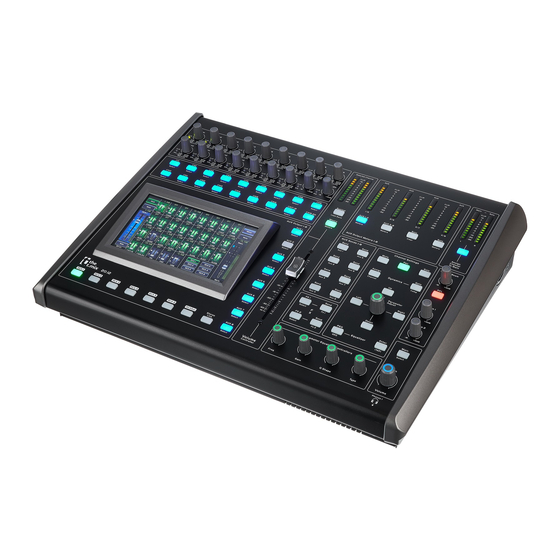
Page 10: Connections And Controls
Connections and controls Connections and controls Overview A Settings for the inputs B Settings for tone and signal processing C Settings for the outputs mixer... - Page 11 Connections and controls Front panel 1 7" touch screen 2 [Select] Selects the respective channel to perform tone control and assignment to outputs. 3 [Sig/Clip] The LED lights up green when a signal is present at the respective input (level > -30 dB). The LED lights up red when the signal level is too high and distortion due to clipping occur (level >...
- Page 12 Connections and controls 10 [System / Load Save] Opens the system menu and the menus for loading or saving presets one by one 11 [Selected Channel] Level meter for currently selected input channel. 12.13 [AUX / AUX 1-4 / Meters], [AUX / AUX 5-8 / Meters] Level meters, switchable between the buses AUX1…AUX8 with the respective buttons.
- Page 13 Connections and controls 26 [Phones 1 / Phones 2] Volume control for the headphones outputs 27 [Parameter Adjust] Control to set the main parameter of the currently selected effect. By pressing [Up], [Down], [Left] and [Right] you can navigate the display pages. 28 [Main / Select] Selects the Main bus to perform tone control and assignment to outputs.
- Page 14 Connections and controls Rear panel 40 [Mic/Line 1]…[Mic/Line 16] Inputs for microphone level signals and line level signals, designed as XLR / 1/4" combo jacks. 41 [HP2] Monitor output for headphones, designed as 1/4" phone socket (stereo). 42 [Insert] 1/4" jacks for looping external effects into the signal path, available for input channels 1…8. 43 [Ethernet] RJ45 socket for the integration of the device into a local area network (LAN) or for firmware updates.
- Page 15 Connections and controls 49 [Input] IEC chassis plug for operating voltage supply with fuse holder. Should the fuse have blown, disconnect the unit from the power supply and replace the fuse with a new fuse of the same type. 50 [AUX Outputs] AUX outputs 1…8, designed as 1/4"...
-
Page 16: Operating
Operating Operating 6.1 Main menu In the main menu, important settings are directly accessible. Press [System / Load Save]. ð The main menu appears on the display. Use the display to select, set values, and navigate the menu. The table below shows on overview of the available menus. Menu item Meaning ‘Assign / C Strip’... - Page 17 Operating Menu item Meaning ‘System / Routing’ Tapping the ‘System / Routing’ button switches between ‘System’ and ‘Routing’ function. ‘System’ Displays information about the hardware and software revision status and allows the device to be reset to the factory defaults. ‘Routing’...
-
Page 18: Parametric Equalizer
Operating 6.2 Parametric Equalizer For each input channel and each output channel, a parametric equalizer with four frequency bands plus high-pass and low-pass filters can be switched on. Tap the ‘PEQ / GEQ’ button to change to the ‘PEQ’ function. Press one of the [CH] buttons for an input channel, one of the [AUX] buttons for an output channel, or the buttons [FX 1] or [FX 2]. -
Page 19: Graphic Equalizer
Operating Option Selection range Meaning ‘Q’ 0.4 – 24 Q shape of EQ band ‘Gain’ –24 – +24 dB Boost / cut 6.3 Graphic Equalizer For the outputs MAIN and AUX, a 31-band equalizer can be switched on. Tap the ‘PEQ / GEQ’ button to change to the ‘GEQ’ function. Press one of the [AUX] buttons for an output channel. -
Page 20: Compressor
Operating 6.4 Compressor For each input channel and each output channel, a compressor can be switched on. Tap the ‘Comp / Gate’ button to change to the ‘Comp’ function. Press one of the [CH] buttons for an input channel, one of the [AUX] buttons for an output channel, or the buttons [FX 1] or [FX 2]. -
Page 21: Noise Gate
Operating 6.5 Noise Gate For each input channel a noise gate can be switched on. Tap the ‘Comp / Gate’ button to change to the ‘Gate’ function. Press one of the [CH] buttons for an input channel, one of the [AUX] buttons for an output channel, or the buttons [FX 1] or [FX 2]. -
Page 22: Technical Specifications
Technical specifications Technical specifications Input level (Mic / Line) XLR / 1/4" combo jacks (balanced): max. +22 dBu Input impedance Mic/Line: 1.4 kΩ Total harmonic distortion (THD) < 0.01 %1 kHz Frequency range 20 Hz…20 kHz, 0 dBu ±1.5 dB Signal-to-noise ratio 104 dB Gain... - Page 23 Technical specifications Block diagram 20.12...
-
Page 24: Plug And Connection Assignment
Plug and connection assignment Plug and connection assignment Introduction This chapter will help you select the right cables and plugs to connect your valuable equipment in such a way that a perfect sound experience is ensured. Please note these advices, because especially in ‘Sound & Light’ caution is indicated: Even if a plug fits into the socket, an incorrect connection may result in a destroyed power amp, a short circuit or ‘just’... - Page 25 Plug and connection assignment XLR plug (balanced) Ground, shielding Signal (in phase, +) Signal (out of phase, –) Shielding on plug housing (option) 20.12...
-
Page 26: Cleaning
Cleaning Cleaning Fan grids The fan grids of the device must be cleaned on a regular basis to remove dust and dirt. Before cleaning, switch off the device and disconnect AC-powered devices from the mains. Use a lint-free damp cloth for cleaning. Never use solvents or alcohol for cleaning. -
Page 27: Protecting The Environment
Protecting the environment Protecting the environment Disposal of the packaging material For the transport and protective packaging, environmentally friendly materials have been chosen that can be supplied to normal recycling. Ensure that plastic bags, packaging, etc. are properly disposed of. Do not just dispose of these materials with your normal household waste, but make sure that they are collected for recycling. - Page 28 Notes mixer...
- Page 29 Notes 20.12...
- Page 30 Notes mixer...
- Page 32 Musikhaus Thomann · Hans-Thomann-Straße 1 · 96138 Burgebrach · Germany · www.thomann.de...
Need help?
Do you have a question about the The t.mix 20.12 and is the answer not in the manual?
Questions and answers