Table of Contents
Advertisement
Advertisement
Table of Contents

Related Manuals for thomann t.mix mix 1402FX


Summary of Contents for thomann t.mix mix 1402FX
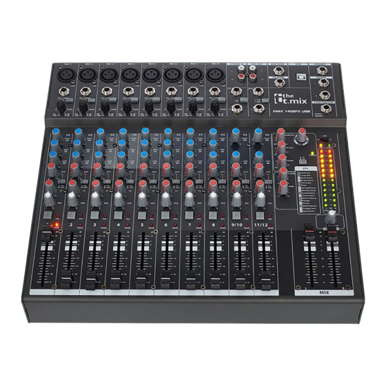
- Page 1 mix 1402FX mixer user manual...
- Page 2 Musikhaus Thomann Thomann GmbH Hans-Thomann-Straße 1 96138 Burgebrach Germany Telephone: +49 (0) 9546 9223-0 E-mail: info@thomann.de Internet: www.thomann.de 23.01.2017, ID: 401658...
-
Page 3: Table Of Contents
Table of contents Table of contents General information..........................4 1.1 Further information........................... 5 1.2 Notational conventions........................6 1.3 Symbols and signal words....................... 6 Safety instructions............................. 8 Features............................... 13 Installation and starting up........................ 14 Connections and controls........................15 Technical specifications........................33 Plug and connection assignment.................... -
Page 4: General Information
General information General information This manual contains important instructions for the safe operation of the unit. Read and follow the safety instructions and all other instructions. Keep the manual for future reference. Make sure that it is available to all those using the device. If you sell the unit please make sure that the buyer also receives this manual. -
Page 5: Further Information
General information 1.1 Further information On our website (www.thomann.de) you will find lots of further information and details on the following points: Download This manual is also available as PDF file for you to download. Use the search function in the electronic version to find the topics of Keyword search interest for you quickly. -
Page 6: Notational Conventions
General information 1.2 Notational conventions This manual uses the following notational conventions: Letterings The letterings for connectors and controls are marked by square brackets and italics. Examples: [VOLUME] control, [Mono] button. 1.3 Symbols and signal words In this section you will find an overview of the meaning of symbols and signal words that are used in this manual. - Page 7 General information Signal word Meaning DANGER! This combination of symbol and signal word indicates an immediate dangerous situation that will result in death or serious injury if it is not avoided. CAUTION! This combination of symbol and signal word indicates a pos‐ sible dangerous situation that can result in minor injury if it is not avoided.
-
Page 8: Safety Instructions
Safety instructions Safety instructions Intended use This device is intended to be used for amplification, mixing and playback of signals from musical instruments and microphones. Use the device only as described in this user manual. Any other use or use under other operating conditions is considered to be improper and may result in personal injury or property damage. - Page 9 Safety instructions Safety DANGER! Danger for children Ensure that plastic bags, packaging, etc. are disposed of properly and are not within reach of babies and young children. Choking hazard! Ensure that children do not detach any small parts (e.g. knobs or the like) from the unit.
- Page 10 Safety instructions DANGER! Electric shock caused by short-circuit Always use proper ready-made insulated mains cabling (power cord) with a pro‐ tective contact plug. Do not modify the mains cable or the plug. Failure to do so could result in electric shock/death or fire. If in doubt, seek advice from a regis‐ tered electrician.
- Page 11 Safety instructions NOTICE! Risk of fire Do not cover the device nor any ventilation slots. Do not place the device near any direct heat source. Keep the device away from naked flames. NOTICE! Operating conditions This device has been designed for indoor use only. To prevent damage, never expose the device to any liquid or moisture.
- Page 12 Safety instructions NOTICE! Power supply Before connecting the device, ensure that the input voltage (AC outlet) matches the voltage rating of the device and that the AC outlet is protected by a residual current circuit breaker. Failure to do so could result in damage to the device and possibly injure the user.
-
Page 13: Features
Features Features 14-channel mixer with built-in FX processor 8 mono channels (MIC, line) with switchable Low-Cut, 3-band EQ and Panorama control 2 stereo channels (line) with 2-band EQ and Balance control 1 × AUX control per channel, PRE/POST selectable PFL switch per channel Master output L/R via 2 ×... -
Page 14: Installation And Starting Up
Installation and starting up Installation and starting up Unpack and carefully check that there is no transportation damage before using the unit. Keep the equipment packaging. To fully protect the device against vibration, dust and moisture during transportation or storage use the original packaging or your own packaging material suitable for transport or storage, respectively. -
Page 15: Connections And Controls
Connections and controls Connections and controls Mono channel strip mix 1402FX... - Page 16 Connections and controls 1 [MIC] Balanced XLR mono input to connect a microphone. 2 [LINE] 1/4" phone input to connect a line level audio source (keyboards, drum modules etc., balanced or unbalanced). 3 [80 Hz HPF] High pass filter to attenuate rumble noise and other low frequency interference. 4 [GAIN] Rotary control to adjust the input level.
- Page 17 Connections and controls 8 [FX] Rotary control to control the signal portion, which is sent to the internal effects section as well as to the [FX SEND] output. 9 [PAN] Rotary control to arrange the channel signal within the stereo panorama R / L. 10 [PFL] switch With this switch pressed, the channel signal is unaffectedly by the setting of the channel fader and the internal effects section and present at the outputs [PHONES] and [CR OUT] .
- Page 18 Connections and controls Stereo channel strip mixer...
- Page 19 Connections and controls 14 [L] 1/4" phone input to connect the left signal of a stereo line level audio source (keyboards, drum modules etc.). With mono signals in channel 11/12, use this input with the [R] socket unused so the signal is present at both sum chan‐ nels.
- Page 20 Connections and controls 19 [AUX] Rotary control to adjust the signal portion to be sent to the [AUX SEND] output to e.g. create a monitor mix. 20 [PRE / POST] When this switch is pressed, the signal portion set with the [AUX] control is not affected by the channel fader ([PRE]). When the switch is not pressed, the AUX signal is not subject to the channel fader ([POST]).
- Page 21 Connections and controls 25 [PEAK] The LED lights up on channel overload. If this happens in channel 9/10 press the [PAD] switch. When overload occurs in channel 11/12 reduce the output level of the signal source connected here. 26 The channel fader sets the strength of the channel signal in the overall signal. mix 1402FX...
- Page 22 Connections and controls Effects section, AUX mixer...
- Page 23 Connections and controls 27 [PARAMETER] Rotary control to set the main parameter of the currently selected effect. 28 [1 - 16] Rotary control to select the desired effect, see list [EFX.] printed beneath the ‘ON | OFF’ switch. 29 [FX TO AUX] Rotary control to adjust the effects portion present at the output [AUX SEND] .
- Page 24 Connections and controls 33 [AUX SEND] Rotary control to adjust the overall level at the [AUX SEND] output. 34 [FX SEND] Rotary control to adjust the overall level at the [FX SEND] output. mixer...
- Page 25 Connections and controls Master section mix 1402FX...
- Page 26 Connections and controls 35 [STEREO IN] Stereo RCA input for line level audio sources. 36 [REC OUT] Stereo RCA output for line level audio sources. Here, the sum signal is present, but unaffected by the master faders. 37 [AUX SEND] At this line level output the signal set with the [AUX] channel controls is present, maybe to create a monitor mix.
- Page 27 Connections and controls 41 [CR OUT] Outputs to connect studio monitors, e.g. active speakers or a stereo power amplifier with passive speakers. 42 [FOOT SWITCH] Connector for a foot switch to turn the internal effects section on or off. 43 [+48V] switch When this switch is in the ON position, a phantom voltage of 48 V is present at the XLR sockets in the mono channels for using condenser mics.
- Page 28 Connections and controls 46 [LEDs] These LED chains indicate the level of the sum signal. Keep the level within a range below +18. The red LEDs indicates overload. In this case, pull back the two master faders so that the red LEDs do not light up any more. If the PFL button is pressed in one of the channels, the signal in this channel is displayed in the left LED chain, regardless of the channel fader.
- Page 29 Connections and controls Rear panel 50 [MAIN OUTPUTS] Balanced 1/4" phone outputs for connecting power amplifiers, effects or recording devices. 51 [MAIN OUTPUTS] Balanced XLR outputs for connecting power amplifiers, effects or recording devices. mix 1402FX...
- Page 30 Connections and controls 52 [POWER] Mains switch to turn the device on or off. 53 [SIGNAL] IEC chassis connector for mains connection with fuse holder. To replace the fuse, carefully take out the fuse holder with a small screwdriver, replace the defective fuse with a new one of the same type and push the fuse holder back in until it snaps into place.
- Page 31 Connections and controls Connection pattern – club gig mix 1402FX...
- Page 32 Connections and controls Connection pattern – PC home recording mixer...
-
Page 33: Technical Specifications
Technical specifications Technical specifications Max. output level, balanced (1% THD MAIN OUTPUT +26 dBu ± 1 dBu @ 1 kHz) Max. output level, unbalanced MAIN OUTPUT +21 dBu ± 1 dBu (1% THD @ 1 kHz) Headphones output 150 mW ± 5 mW @ 32 Ω Distortion (THD + N) <0.025% @ +14 dBu ±... - Page 34 Technical specifications all balanced outputs 200 Ω Signal gain mono channel 44 dB adjustable mic input (-16 ~ -60 dB) Line (-10 dB ~ +34 dB) Treble +/- 10 dB, ± 1.5 dB @ 12 kHz shelving Mids +/- 10 dB, ± 1.5 dB @ 1 kHz shelving Bass +/- 10 dB, ±...
-
Page 35: Plug And Connection Assignment
Plug and connection assignment Plug and connection assignment Introduction This chapter will help you select the right cables and plugs to connect your valuable equip‐ ment in such a way that a perfect sound experience is ensured. Please note these advices, because especially in ‘Sound & Light’ caution is indicated: Even if a plug fits into the socket, an incorrect connection may result in a destroyed power amp, a short circuit or ‘just’... - Page 36 Plug and connection assignment Since the interference affects both cores equally, by subtracting the phase-shifted signals, the interfering signal is completely neutralized. The result is a pure signal without any noise inter‐ ference. 1/4" TS phone plug (mono, unbalanced) Signal Ground, shielding 1/4"...
- Page 37 Plug and connection assignment 1/4" TRS phone plug (stereo, unbalanced) Signal (left) Signal (right) Ground XLR plug (balanced) Ground, shielding Signal (in phase, +) Signal (out of phase, –) mix 1402FX...
- Page 38 Plug and connection assignment XLR plug (unbalanced) Ground, shielding Signal Bridged to pin 1 RCA connection Drawing and table indicate the pin assignment of an RCA plug. Signal Ground, shielding mixer...
-
Page 39: Protecting The Environment
Protecting the environment Protecting the environment Disposal of the packaging mate‐ rial For the transport and protective packaging, environmentally friendly materials have been chosen that can be supplied to normal recycling. Ensure that plastic bags, packaging, etc. are properly disposed of. Do not just dispose of these materials with your normal household waste, but make sure that they are collected for recycling. - Page 40 Notes mixer...
- Page 41 Notes mix 1402FX...
- Page 42 Notes mixer...
- Page 44 Musikhaus Thomann · Hans-Thomann-Straße 1 · 96138 Burgebrach · Germany · www.thomann.de...
Need help?
Do you have a question about the t.mix mix 1402FX and is the answer not in the manual?
Questions and answers