Table of Contents
Advertisement
Quick Links
UM11038
OM27642 Smart Lock KIT
Rev. 1.1 — 11 October 2018
407611
Document information
Info
Content
Keywords
OM27462NBR Smart Lock KIT User manual
Abstract
This document describes the content, the hardware implementation and
the usage of the Android application as well as the access token structure
and processing of the NFC Bluetooth
OM27462NBR. It also describes how to update the QN9021 and PN7462
firmware.
User manual
COMPANY PUBLIC
®
Low Energy Smart Lock KIT -
Advertisement
Table of Contents

Subscribe to Our Youtube Channel
Related Manuals for NXP Semiconductors OM27642


Summary of Contents for NXP Semiconductors OM27642
- Page 1 UM11038 OM27642 Smart Lock KIT Rev. 1.1 — 11 October 2018 User manual 407611 COMPANY PUBLIC Document information Info Content Keywords OM27462NBR Smart Lock KIT User manual Abstract This document describes the content, the hardware implementation and the usage of the Android application as well as the access token structure ®...
- Page 2 UM11038 NXP Semiconductors OM27642 Smart Lock KIT Revision history Date Description • 20181011 Fig. 14 updated • Editorial updates 20161116 First release Contact information For more information, please visit: http://www.nxp.com UM11038 All information provided in this document is subject to legal disclaimers.
-
Page 3: Introduction
UM11038 NXP Semiconductors OM27642 Smart Lock KIT 1. Introduction ® This document describes the implementation of a battery-operated Bluetooth Low Energy NFC Smart Lock for the hospitality market. This document does not replace the PN7462AU or QN9021 datasheets and respective application notes. Please refer to the datasheets for detailed information of the ICs. -
Page 4: Smart Lock Kit Package Content
UM11038 NXP Semiconductors OM27642 Smart Lock KIT 2. Smart Lock KIT Package Content Fig 1. OM27462NBR Smart Lock module, power cable, programming cable, touch sensor plate, set of demonstration cards UM11038 All information provided in this document is subject to legal disclaimers. -
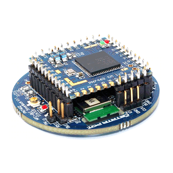
Page 5: Smart Lock Module Hardware
UM11038 NXP Semiconductors OM27642 Smart Lock KIT 3. Smart Lock Module Hardware Fig 2. OM27462NBR Smart Lock module consisting of PN7462AU core module V1.2 and the 40mm Ø base board NFC- Bluetooth Low Energy Smart Lock V1.1 The core module – stack on board contains all necessary blocking capacitors, XTAL, 2 status LEDs and the antenna EMC filter. -
Page 6: Smart Lock System Block Diagram
UM11038 NXP Semiconductors OM27642 Smart Lock KIT 3.1 Smart lock system block diagram Fig 3. Main building blocks Fig 4. OM27462NBR NFC- Bluetooth Low Energy Module with PN7462 stack on core module Figure 4 shows the functional block diagram of the Smart Lock module including the main components used. -
Page 7: Schematics
UM11038 NXP Semiconductors OM27642 Smart Lock KIT 4. Schematics Fig 5. Base board schematic part 1 UM11038 All information provided in this document is subject to legal disclaimers. © NXP B.V. 2018. All rights reserved. User manual Rev. 1.1 — 11 October 2018... -
Page 8: Base Board Schematics Continued
UM11038 NXP Semiconductors OM27642 Smart Lock KIT 4.1 Base board schematics continued Fig 6. Base board schematic part 2 UM11038 All information provided in this document is subject to legal disclaimers. © NXP B.V. 2018. All rights reserved. User manual Rev. -
Page 9: Core Module Schematics
UM11038 NXP Semiconductors OM27642 Smart Lock KIT 4.2 Core Module schematics Fig 7. Core Module pin out vs. PN7462AU pin out UM11038 All information provided in this document is subject to legal disclaimers. © NXP B.V. 2018. All rights reserved. -
Page 10: Antenna Matching
UM11038 NXP Semiconductors OM27642 Smart Lock KIT 4.3 Antenna matching The antenna matching of the Smart Lock main PCB is shown below. The EMC filter is part of the stack-on core Module. The base board consists of the matching circuit with the damping resistors and the serial and parallel matching capacitors. -
Page 11: Base Board Connectors
UM11038 NXP Semiconductors OM27642 Smart Lock KIT 5. Base board connectors Fig 10. Base board connection description 6. Getting started 6.1 Setting up the hardware module 1) Connect the Touch sensor plate as shown in fig. 1. 2) Connect a DC power source (2V-3.3V) to the pins labeled “BAT” (see fig. 1) 6.1.1 Smart Lock power connection... -
Page 12: Smart Lock Operation
UM11038 NXP Semiconductors OM27642 Smart Lock KIT 7. Smart Lock operation The Smart Lock KIT comes with pre-configured functionality. 7.1 Operating the Smart Lock using the demonstration cards 1) Configure Room 201 by bringing the “Lock Configuration Room 201” card in close proximity of the module. -
Page 13: Operating The Smart Lock Using The Mobile Smart Lock App
UM11038 NXP Semiconductors OM27642 Smart Lock KIT 7.2 Operating the Smart Lock using the mobile Smart Lock App Download the “NXP SMARTLOCK” app from Google Play Store and install it on your mobile NFC enabled Android device. Fig 13. Download link Google Playstore UM11038 All information provided in this document is subject to legal disclaimers. - Page 14 UM11038 NXP Semiconductors OM27642 Smart Lock KIT Fig 14. Quick reference for Smart Lock App UM11038 All information provided in this document is subject to legal disclaimers. © NXP B.V. 2018. All rights reserved. User manual Rev. 1.1 — 11 October 2018...
-
Page 15: Firmware Design Description
UM11038 NXP Semiconductors OM27642 Smart Lock KIT 8. Firmware design description 8.1 Power saving As RFID and Bluetooth Low Energy Smart Lock Reference Design is powered by a battery it is important that we consume as little energy as possible. The PN spends most of its time shut down and can be woken in multiple ways: •... -
Page 16: Communication Protocol Between Qn And Pn
UM11038 NXP Semiconductors OM27642 Smart Lock KIT 9. Communication protocol between QN and PN Communication between QN and PN is done using two GPIO lines and UART communication (115200 bps and data format 8N1). The GPIO lines are used to power the PN (in case a Bluetooth Low Energy client connects) or to wake-up QN (in case a card or phone is presented to the PN via NFC). -
Page 17: Handshake Between The Qn And Pn
UM11038 NXP Semiconductors OM27642 Smart Lock KIT 10. Handshake between the QN and PN According to the use cases NFC and Bluetooth Low Energy communication, two scenarios exist to start the communication between QN and PN 10.1.1 NFC Transaction In this use case the PN is powered up either by the proximity switch or the micro switch. -
Page 18: Bluetooth Low Energy Transaction
UM11038 NXP Semiconductors OM27642 Smart Lock KIT 10.1.2 Bluetooth Low Energy Transaction In this use case QN will power PN using the BLE_OUT line after establishing the Bluetooth Low Energy connection. After power on the PN will start the communication by triggering the QN GPIO interrupt using the BLE_DETECT line. -
Page 19: Data Exchange
UM11038 NXP Semiconductors OM27642 Smart Lock KIT 10.2 Data exchange After the initial handshake data exchange may start. The following commands are available: • ‘C’: PN sends APDU command to QN (QN forwards data to the Bluetooth Low Energy client) •... -
Page 20: Structure Of The Qn Firmware
UM11038 NXP Semiconductors OM27642 Smart Lock KIT 11. Structure of the QN Firmware The QN firmware is built on NXP Bluetooth Low Energy library. This library implements a proprietary profile which is optimized sending and receiving APDU commands. It automatically splits data onto several Bluetooth Low Energy packets if necessary. In addition, the library uses the Bluetooth Low Energy feature to send several Bluetooth Low Energy packets in one communication interval to speed up communication. -
Page 21: Src\Driver\Pn_Nfc.c
UM11038 NXP Semiconductors OM27642 Smart Lock KIT the QN is ready to accept commands from PN like reconfiguring the device name (e.g. room number is changed). The main handlers in active state are the functions • pn_uart_rx_ind_handler() It processes messages sent from the pn driver and thus evaluates the commands received from PN. -
Page 22: Interaction With Bluetooth Low Energy Stack
UM11038 NXP Semiconductors OM27642 Smart Lock KIT 11.3 Interaction with Bluetooth Low Energy Stack NXP Bluetooth Low Energy Lib only needs few interfaces to exchange data with the Bluetooth Low Energy Client. When the Bluetooth Low Energy Client sends a BLE write... -
Page 23: Smart Lock\Smart Lock .C
UM11038 NXP Semiconductors OM27642 Smart Lock KIT 11.5 Smart Lock\Smart Lock .c The file contains the main state machine for UART-to- Bluetooth Low Energy communication. As described there are two main states: 1) power-on-handshake 2) data exchange 11.6 Power-On-Handshake The sequence begins after Bluetooth Low Energy receives new connection in the... -
Page 24: Structure Of The Pn Firmware
UM11038 NXP Semiconductors OM27642 Smart Lock KIT 12. Structure of the PN Firmware PN firmware is split into two tasks: 1) CLIF – RFID task (implemented in smart_lock_clif.c) 2) HIF – UART task (implemented in smart_lock_hif.c) The tasks are created in the appMain function in src/smart_lock.c. -
Page 25: Task Clif Nxprdlib Component Stack For Communication
UM11038 NXP Semiconductors OM27642 Smart Lock KIT Task CLIF NxpRdLib component stack for communication: phhalHw_Nfc_Ic_DataParams_t phpalI14443p4_Sw_DataParams_t phpalMifare_Sw_DataParams_t phalMfdf_Sw_DataParams_t phKeyStore_Sw_DataParams_t phCryptoSym_Sw_DataParams_t phCryptoRng_Sw_DataParams_t 12.3 Task HIF Task HIF is implemented in smart_lock_task_hif.c. After the task starts it initializes custom BAL and HAL layers that implement QN ↔ PN communication protocol. Next it tries to perform the handshake between the QN and PN. -
Page 26: Configuration Options For Pn Firmware
UM11038 NXP Semiconductors OM27642 Smart Lock KIT 12.4 Configuration options for PN firmware PN firmware can be configured in different ways by means of defines in smart_lock_cfg.h in the following ways: • Cryptographic algorithm configuration options: ◦ SMART_LOCK_CFG_AUTH_2KTDES ◦ SMART_LOCK_CFG_AUTH_3KTDES ◦... -
Page 27: Flash New Firmware On Pn
UM11038 NXP Semiconductors OM27642 Smart Lock KIT Fig 18. LPC Link2 SWD connection cable 13.3 Flash new firmware on PN • Install LPCXpresso IDE and activate the free edition under HelpActivateActivate (Free Edition) • Install LPCXpresso PN7462AU plugin • Import the Smartlock PN Project via FileImportExisting Project into Workspace •... -
Page 28: Flash New Firmware On Qn
UM11038 NXP Semiconductors OM27642 Smart Lock KIT 13.4 Flash new firmware on QN 13.4.1 Flash with LPC Link 2 • Install ARM Keil MDK • Install the QN9020QBlue Software tools • Run the QN9020DevDBforIDE tool to install the Keil QN Device Database •... - Page 29 UM11038 NXP Semiconductors OM27642 Smart Lock KIT A new Window should open and show the SW Device in the List. Device Name should be “ARM CoreSight SW-DP” as in Fig 20. Fig 20. Configure Debug Adapter in Keil Also ensure that CMSIS-DAP Debugger is selected as Target Driver in the Utilities Settings and the Settings are matching with the Fig 20.
- Page 30 UM11038 NXP Semiconductors OM27642 Smart Lock KIT Fig 21. Configure Utilities in Keil Save the settings with OK. Now you should be able to flash the QN via FlashDownload UM11038 All information provided in this document is subject to legal disclaimers.
-
Page 31: Flash With Serial
UM11038 NXP Semiconductors OM27642 Smart Lock KIT 13.4.2 Flash with serial Optional it is also possible to flash the QN via a serial port. Remove the PN Core module and connect your serial port with the QN as shown in the Fig 22. -
Page 32: Hospitality Access Token
UM11038 NXP Semiconductors OM27642 Smart Lock KIT 14. Hospitality Access Token 14.1 Overview Fig 24. Harmonized data structure 14.2 MIFARE DESFire card configuration 14.2.1 Application configuration: • Application Master Key Setting: 0x0B (Change App Key, GetFile enabled, master key changeable) 14.2.2 Application Key settings:... -
Page 33: Standard Data File Settings
UM11038 NXP Semiconductors OM27642 Smart Lock KIT 14.2.4 Standard Data File settings • File ID: 0x00 • Supported Communication Modes • Fully Encrypted • Access rights: 0x1000 • Key #0 for write, R&W, Change Access rights • Key #1 for read •... -
Page 34: Power Consumption Figures
UM11038 NXP Semiconductors OM27642 Smart Lock KIT 15. Power consumption figures The above table shows different power consumption figures based on Bluetooth Low Energy advertising intervals. The current QN firmware implementation is configured for 600ms -14 dBm. at around 93 µA while advertising. -
Page 35: Legal Information
NXP Semiconductors product can reasonably be expected Purchase of an NXP Semiconductors IC that complies with one of the Near to result in personal injury, death or severe property or environmental Field Communication (NFC) standards ISO/IEC 18092 and ISO/IEC 21481 damage. -
Page 36: Trademarks
UM11038 NXP Semiconductors OM27642 Smart Lock KIT AMBA, Arm, Arm7, Arm7TDMI, Arm9, Arm11, Artisan, big.LITTLE, 19.4 Trademarks Cordio, CoreLink, CoreSight, Cortex, DesignStart, DynamIQ, Jazelle, Keil, Mali, Mbed, Mbed Enabled, NEON, POP, RealView, SecurCore, Notice: All referenced brands, product names, service names and Socrates, Thumb, TrustZone, ULINK, ULINK2, ULINK-ME, ULINK-PLUS, trademarks are property of their respective owners. -
Page 37: Table Of Contents
UM11038 NXP Semiconductors OM27642 Smart Lock KIT 20. Contents 11.6 Power-On-Handshake ........23 Introduction ............3 11.7 Data exchange ..........23 Smart Lock KIT Package Content ...... 4 11.7.1.1 Send data ............23 Smart Lock Module Hardware ......5 11.7.1.2 Receive data ............ 23 Smart lock system block diagram ....... - Page 38 UM11038 NXP Semiconductors OM27642 Smart Lock KIT Power consumption figures ......34 Power optimization considerations ....34 Download available Documents and firmware 34 References ............34 Legal information ..........35 19.1 Definitions ............35 19.2 Disclaimers............35 19.3 Licenses ............35 19.4...
Need help?
Do you have a question about the OM27642 and is the answer not in the manual?
Questions and answers