
Related Manuals for NXP Semiconductors LPC54018


Summary of Contents for NXP Semiconductors LPC54018
- Page 1 UM11078 LPC54018 IoT module Rev. 1.2 — 20 March 2018 User manual Document information Info Content Keywords LPC54018, OM40007, Amazon FreeRTOS, AWS, GT1216 Abstract LPC54018 IoT module user manual...
- Page 2 UM11078 NXP Semiconductors LPC54018 IoT module Revision history Date Description 20171206 Initial release 20171205 Added FreeRTOS getting started information, improved diagrams. 20180320 Updated Getting started to reflect MCUXpresso SDK support now available. Contact information For more information, please visit: http://www.nxp.com For sales office addresses, please send an email to: salesaddresses@nxp.com...
-
Page 3: Introduction
NXP Semiconductors LPC54018 IoT module 1. Introduction The LPC54018 IoT module, developed by NXP in partnership with Embedded Artists, is self-contained, high performance, IEEE802.11 enabled microcontroller module for the development of products utilizing Amazon FreeRTOS or other IoT platforms. The module can be used as a standalone or plugged into a motherboard or baseboard for rapid product development and prototyping. - Page 4 UM11078 NXP Semiconductors LPC54018 IoT module Dual Hirose expansion connectors provide access to wide range of peripherals and memory expansion provided by the LPC54018: • LCD interface with DMA controller, supporting up to 24-bit color • External memory interface, supporting SDRAM, SRAM and/or parallel flash •...
-
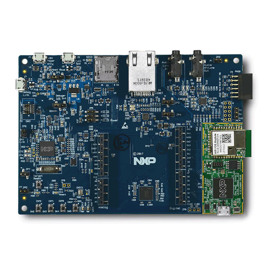
Page 5: Board Layout
NXP’s website (http://www.nxp.com/demoboard/OM40007) under the Software and Tools and/or Getting Started tabs. Code can be downloaded and debugged on the LPC54018 MCU using a debug probe that conforms to the standard Arm Cortex 10-pin debug connector. Amazon FreeRTOS and MCUXpresso SDK packages are available for MCUXpresso IDE, IAR EWARM and Keil MDK at https://mcuxpresso.nxp.com. -
Page 6: Attaching The Debug Probe And Powering Up (Baseboard Not Used)
UM11078 NXP Semiconductors LPC54018 IoT module The module may also be mounted on to an OM40006 baseboard from Embedded Artists. This baseboard includes an on-board LPC-Link2 debug probe, which can be programmed to support either CMSIS-DAP or SEGGER J-Link protocols - all tool chains mentioned above will support either of these protocols (note that CMSIS-DAP is required to use SWO trace/profiling and data watch features with MCUXpresso IDE). -
Page 7: Expansion Connectors
Figure 6. Note that many port pins of the LPC54018 can be configured to one of the several functions. So, a baseboard designed to receive the module may use different functions shown on the labels in these diagrams. For full information on I/O configuration, refer to the user manual for the LPC540xx family devices. - Page 8 UM11078 NXP Semiconductors LPC54018 IoT module Fig 5. J3 expansion connector (Pin 51 to Pin 100) UM11078 All information provided in this document is subject to legal disclaimers. © NXP B.V. 2018. All rights reserved. User manual Rev. 1.2 — 20 March 2018...
- Page 9 UM11078 NXP Semiconductors LPC54018 IoT module Fig 6. J4 expansion connector (Pin 1 to Pin 50) For further details, refer to the board schematics. UM11078 All information provided in this document is subject to legal disclaimers. © NXP B.V. 2018. All rights reserved.
- Page 10 UM11078 NXP Semiconductors LPC54018 IoT module Fig 7. J4 expansion connector (Pin 51 to Pin 100) UM11078 All information provided in this document is subject to legal disclaimers. © NXP B.V. 2018. All rights reserved. User manual Rev. 1.2 — 20 March 2018...
-
Page 11: Power Supplies
The baseboard should connect this signal to its 3.3 V supply.The module has an FET switch, which is turned off when the baseboard sense is driven to 3.3 V. It effectively separates the LPC54018 VDD from the VDD of other components, allowing its current drawn to be measured separately. -
Page 12: Legal Information
In no event shall NXP Semiconductors be liable for any indirect, incidental, punitive, special or consequential damages (including - without limitation - lost NXP Semiconductors does not accept any liability related to any default,... -
Page 13: Table Of Contents
UM11078 NXP Semiconductors LPC54018 IoT module 8. Contents Introduction ......3 Board layout ......5 Getting started . - Page 14 Mouser Electronics Authorized Distributor Click to View Pricing, Inventory, Delivery & Lifecycle Information: OM40007UL OM40006UL...
Need help?
Do you have a question about the LPC54018 and is the answer not in the manual?
Questions and answers