Table of Contents
Advertisement
Quick Links
Freescale Semiconductor
User Guide
Application Module Student Learning Kit Users
Guide featuring the Freescale MC9S12C32
© Freescale Semiconductor, Inc., 2006. All rights reserved.
_______________________________________________________________________
For use with the following part numbers:
SLK0101UG
Rev. 0, 9/2006
CSM-12C32
APS12C32SLK
PBS12C32SLK
Advertisement
Table of Contents

Subscribe to Our Youtube Channel
Related Manuals for NXP Semiconductors Freescale MC9S12C32


Summary of Contents for NXP Semiconductors Freescale MC9S12C32
- Page 1 Freescale Semiconductor SLK0101UG User Guide Rev. 0, 9/2006 Application Module Student Learning Kit Users Guide featuring the Freescale MC9S12C32 For use with the following part numbers: CSM-12C32 APS12C32SLK PBS12C32SLK © Freescale Semiconductor, Inc., 2006. All rights reserved. _______________________________________________________________________...
-
Page 2: Table Of Contents
CONTENTS CAUTIONARY NOTES ......................4 FEATURES ..........................5 REFERENCES ...........................6 INTRODUCTION ........................7 GETTING STARTED........................7 OPERATION ..........................7 POWER ..........................8 PWR ..........................8 CONNECTOR J1....................... 8 PWR_SEL JUMPER......................8 RESET SWITCH ........................9 LOW-VOLTAGE DETECT ..................... 9 TIMING ..........................9 COMMUNICATIONS ......................9 COM CONNECTOR ...................... - Page 3 FIGURES Figure 1: PWR_SEL ........................8 Figure 2: COM Connector......................10 Figure 3: MCU_PORT Connector .....................11 Figure 4: BDM_PORT.......................16 TABLES Table 1: Serial COM Signals ....................10 Table 2: User Option Jumper Settings..................11 Table 4: Monitor Commands ....................13 Table 5: Monitor Memory Map....................12 Table 6: MON12 Interrupt Vector Table..................14 Table 7: Serial Monitor Memory Map..................15 REVISION...
-
Page 4: Cautionary Notes
Cautionary Notes ♦ Electrostatic Discharge (ESD) prevention measures should be used when handling this product. ESD damage is not a warranty repair item. ♦ Axiom Manufacturing does not assume any liability arising out of the application or use of any product or circuit described herein; neither does it convey any license under patent rights or the rights of others. -
Page 5: Features
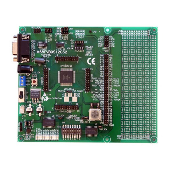
FEATURES The APS12C32SLK is an educational application module for the Freescale Semiconductor MC9S12C32 microcontroller. Application module SLK’s include components for out-of-box operation and are preprogrammed with a serial monitor to make application development quick and easy. A background DEBUG port is provided for development tool use and is compatible with HCS12 BDM interface cables and software. -
Page 6: References
References Reference documents are provided on the support CD in Acrobat Reader format. More information can be found in the Application Notes section of the Freescale Web site. APS12C32SLKSCHEM.pdf APS12C32SLK Application Module Schematic APS12C32SLKUG.pdf APS12C32SLK User Guide 9S12C32DGV1.pdf MC9S12C32 Device User Guide 9S12C32_ZIP.zip Zip file containing Device Block User Guides APS12C32SLKQSUG.pdf... -
Page 7: Introduction
The APS12C32SLK Educational Module is a fully assembled, fully functional module supporting Freescale MC9S12C32 microcontroller. The module comes with a serial cable, power supply, and an embedded monitor for stand-alone operation. Support software for this module is provided for Windows 95/98/NT/2000/XP operating systems. -
Page 8: Power
Power Power is supplied to the module through a 2.0mm barrel connector at location PWR for stand- alone operation. The module may also be powered through connector J1 when connected to the PBMCUSLK. Power may be sourced off-module through connector J1 to external circuitry. Power routing on the module is determined by the PWR_SEL jumper. -
Page 9: Reset Switch
Reset Switch The RESET switch provides an asynchronous reset input to the MCU. Pressing the RESET switch produces a low-voltage level on the RESET input to the MCU. The low-voltage supervisor (LV1) holds the RESET line low for approximately 150 ms after the pushbutton is released. -
Page 10: Com Connector
Use of the J1 connector to input RS-232 signals requires disabling the on-board RS-232 transceiver. Otherwise, signal corruption may occur. Disabling the on-board transceiver is accomplished by opening cut-traces CT1, and CT2. Simply remove the circuit trace between the cut-trace pads to open the circuit. To restore the circuit functionality, install a 1206 size, 0- ohm, resistor or a short piece of wire across the cut-trace pads. -
Page 11: Connector J1
Connector J1 Connector J1 provides access to APS12C32SLK I/O port signals. Figure 3: MCU_PORT Connector PE1/IRQ* Default Signal Assignments RESET* MCU PORT Signal Disable PS1/TXD MODC/BKGD PS0/RXD PS1/TXD COM1 TXD CT-5 PP5/KWP5 10 NC PS0/RXD COM1 RXD CT-4 PE0/XIRQ* 11 12 NC PE1/IRQ* User1... -
Page 12: Led's
LED’s Two LED’s provide active-low, visual output for user applications. A low voltage level driven out on the appropriate MCU port causes the LED to light. MCU ports PA0 and PB4 drive LED1 and LED2 respectively. Development Support The APS12C32SLK ships from the factory with a serial monitor installed in FLASH. An ASCII monitor is also installed to provide quick and easy debug access to the user. -
Page 13: Monitor Commands
Monitor Commands Table 4: Monitor Commands BF <StartAddress> <EndAddress> [<data>] Block Fill memory range with data BR [<Address>] Set/Display user breakpoints CALL [<Address>] Call user subroutine at <Address> GO [<Address>] Begin/continue execution of user code HELP Display the Mon12 command summary LOAD [P] Load S-Records into memory, P = Paged S2 MD <StartAddress>... -
Page 14: Interrupt Vector Table
Interrupt Vector Table Table 5: MON12 Interrupt Vector Table Ram Interrupt Vector MCU Interrupt Vector TRAP code Vector Address Address Source 0F8A FF8A 0F8C FF8C PWME 0F8E FF8E PTPI 0F90 FF90 C4TX 0F92 FF92 C4RX 0F94 FF94 C4ERR 0F96 FF96 C4WU 0F98 FF98... -
Page 15: Serial Monitor Operation
Ram Interrupt Vector MCU Interrupt Vector TRAP code Vector Address Address Source 0FE6 FFE6 0FE8 FFE8 0FEA FFEA 0FEC FFEC 0FEE FFEE 0FF0 FFF0 0FF2 FFF2 0FF4 FFF4 XIRQ 0FF6 FFF6 0FF8 FFF8 TRAP 0FFA FFFA 0FFC FFFC 0FFE FFFE RESERVED Serial Monitor Operation A serial binary monitor is loaded in the MCU internal flash memory. -
Page 16: Bdm_Port Header
Development Studio and other serial monitor interface IDE’s. The serial monitor is not compatible with ASCII interface programs such as HyperTerm or AxIDE. The monitor supports 23 primitive commands to control the target MCU. To allow a user to specify the address of each interrupt service routine, this monitor redirects interrupt vectors to an unprotected portion of FLASH. - Page 17 How to Reach Us: Home Page: www.freescale.com E-mail: support@freescale.com USA/Europe or Locations Not Listed: Freescale Semiconductor Technical Information Center, CH370 1300 N. Alma School Road Chandler, Arizona 85224 +1-800-521-6274 or +1-480-768-2130 support@freescale.com Information in this document is provided solely to enable system and software implementers to use Freescale Semiconductor products.
Need help?
Do you have a question about the Freescale MC9S12C32 and is the answer not in the manual?
Questions and answers