Advertisement
Advertisement
Table of Contents

Related Manuals for FAAC 950 N


Summary of Contents for FAAC 950 N
- Page 1 950 N...
- Page 2 BRACCIO ARTICOLATO ARTICULATED ARM BRAS ARTICULÉ BRAZO ARTICULADO GELENKARM KNIKARM OPEN OPEN 950N 732708 - Rev. B...
- Page 3 TAVOLA : BRACCIO ARTICOLATO A SPINGERE CON MONTAGGIO OPERATORE SULL’ARCHITRAVE TABLE : ARTICULATED PUSH ARM WITH OPERATOR INSTALLATION ON THE LINTEL TABLE : BRAS ARTICULÉ À POUSSÉE AVEC MONTAGE DE L’OPÉRATEUR SUR LE LINTEAU LÁMINA : BRAZO ARTICULADO DE EMPUJE CON MONTAJE DEL OPERADOR EN EL DINTEL ÜBERSICHT : DRUCKGELENKARM MIT MONTAGE DES ANTRIEBS AM STURZ TEKENING...
- Page 4 TAVOLA : BRACCIO ARTICOLATO A SPINGERE CON MONTAGGIO OPERATORE SULLA PORTA TABLE : ARTICULATED PUSH ARM WITH OPERATOR INSTALLATION ON THE DOOR TABLE : BRAS ARTICULÉ À POUSSÉE AVEC MONTAGE DE L’OPÉRATEUR SUR LA PORTE LÁMINA : BRAZO ARTICULADO DE EMPUJE CON MONTAJE DEL OPERADOR EN LA PUERTA ÜBERSICHT : DRUCKGELENKARM MIT MONTAGE DES ANTRIEBS AM TOR TEKENING...
- Page 5 BRACCIO A PATTINO SLIDING ARM BRAS À PATIN BRAZO DE PATÍN GLEITKUFENARM ARM MET GLIJSCHOEN OPEN 950N - Rev. C 732708...
- Page 6 TAVOLA : BRACCIO A PATTINO L=430 mm CON MONTAGGIO OPERATORE SULL’ARCHITRAVE TABLE : SLIDING ARM L=430 mm WITH OPERATOR INSTALLATION ON THE ARCHITRAVE TABLE : BRAS À PATIN L=430 mm AVEC MONTAGE DE L’OPÉRATEUR SUR LE LINTEAU LÁMINA : BRAZO DE PATÍN L=430 mm CON MONTAJE DEL OPERADOR EN EL DINTEL ÜBERSICHT : GLEITKUFENARM L = 430 mm MIT MONTAGE DES ANTRIEBS AM STURZ TEKENING...
- Page 7 TAVOLA : BRACCIO A PATTINO L=330 mm CON MONTAGGIO OPERATORE SULL’ARCHITRAVE TABLE : SLIDING ARM L=330 mm WITH OPERATOR INSTALLATION ON THE ARCHITRAVE TABLE : BRAS À PATIN L=330 mm AVEC MONTAGE DE L’OPÉRATEUR SUR LE LINTEAU LÁMINA : BRAZO DE PATÍN L=330 mm CON MONTAJE DEL OPERADOR EN EL DINTEL ÜBERSICHT : GLEITKUFENARM L = 330 mm MIT MONTAGE DES ANTRIEBS AM STURZ TEKENING...
-
Page 8: Warnings For The Installer
6) FAAC declines all liability caused by improper use or use other than that for structure, in addition to the devices mentioned at point “16”. -
Page 9: Preliminary Checks
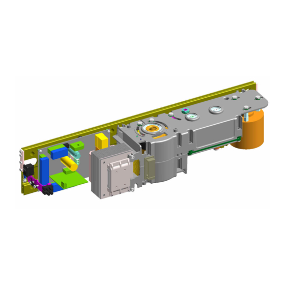
DESCRIPTION AND TECHNICAL SPECIFICA- TIONS Opening adjustable The 950 N automated system for leaf doors is an enbloc from 4 to 10 seconds consisting of an electromechanical device that allows door time opening by means of a transmission arm. The door closes... - Page 10 Fig.1 8. 950 MPS programming unit 1. Cable routing holes 9. Transformer 2. Support proile 10. Mains power supply terminal board 3. 950 I/O unit 11. Housing securing bracket 4. Mechanical stops adjustment 12. Earthing terminal 5. Motion transmission shaft coupling 13.
-
Page 11: Installation
3) Secure the operator using the six M6 screws and washers 3.3 MAXIMUM DOOR OPENING ANGLE in the previously drilled holes, as per the drilling templates ARTICULATED ARM INSTALLATION DOORPOST MAXIMUM 4.2 INSTALLING THE TRANSMISSION ARMS TYPE DEPTH (mm) OPENING It is always advisable to adjust the ANGLE mechanical stops inside the opening/... -
Page 12: Electrical Preparations
For electrical cable installation, use adequate rigid and/or flexible tubes. Always separate the low-voltage accessories connection cables from the power supply cables. To avoid possible interference, use separate sheathing. 1. 950 N Operator 2. Microwave radar / Passive infrared sensor 3. Key release for external use (KEY command) 4. - Page 13 PROGRAMMING THE 950 MPS BOARD 950 MPS Fig.4 DS1 950 MPS SETTING N° FUNCTION NOTE When the door is in “closed” Final closing stroke Disabled Enabled position, allows enabling of a further inal closing stroke. (Useful with electric locks) Articulated arm and/ Sliding arm and/ Set-up procedure or openings up...
- Page 14 950 MPS BOARD CONNECTORS 24V= connector RS232 connector Connector for connecting to the 950 I/0 board Motor connector 950 MPS BOARD TRIMMERS 950 MPS BOARD LEDs TR 1 Opening time adjustment Green LED indicating ( 4 - 10 seconds ) the electric motor power TR 2 Closing time adjustment...
- Page 15 PROGRAMMING AND DESCRIPTION OF THE 950 I/O BOARD 950 I/O BOARD LEDs NOTE Accessories power present No accessories power Card reader active Card reader not active Signals the status of input 17 Internal opening command active Internal opening sensor Signals the status of not active input 10 External opening command active...
- Page 16 950 O/I BOARD CONNECTORS Secondary for transformer Rapid connector for Manual/Night, Open, Automatic mode selector switch Connector for KP CONTROLLER programming unit Common contact for electric lock Normally open contact for activating the electric lock (max contact capacity 0.5A 24V). The contact will close following an open command, during the approximately 70°...
- Page 17 950 I/0 BOARD ELECTRICAL WIRING Fig.7 COMMAND INPUTS 950 I/0 +24 V= INTERNAL OPEN COMMAND (n.o.) EXTERNAL OPEN COMMAND (n.o.) EMERGENCY COMMAND (n.c.) SAFETY COMMAND DURING CLOSING (n.c.) STOP COMMAND DURING OPENING AND CLOSING (n.c.) KEY COMMAND (n.o.) FIRE-PREVENTION COMMAND (n.o.) CARD READER COMMAND CARD READER INPUT (24 V= signal)
-
Page 18: Electric Lock
SAFETY INPUTS 950 I/0 TX= PHOTOCELL TRANSMITTER RX= PHOTOCELL RECEIVER PB SENSOR = STOP SENSOR PHOTOCELLS PB SENSOR Fig.9 ELECTRICAL LOCK COMMAND OUTPUT 950 I/0 N.O. ELECTRIC LOCK 24 V= Fig.10 950N 732708 - Rev. C... - Page 19 ELECTROMAGNET COMMAND OUTPUT 950 I/0 N.C. E L E C T R O M A G N E T 24V= Fig.11 DOOR STATUS OUTPUT (Max contact capacity 0.5 A / 24 V=) 950 I/0 OPEN DOOR N.O. CONTACT CLOSED DOOR N.O. CONTACT (Closes when the door is open) (Closes when the door is closed) Fig.12...
- Page 20 CARD READER CONTACT OUTPUT (Max contact capacity 0.5 A / 24 V=) CARD READER INPUT N.C. CARD READER INPUT 950 I/0 CONTACT N.O. CONTACT (Opens when the card reader (Closes when the card input is active) reader input is active) 20 21 22 Fig.14 MODE SELECTION...
-
Page 21: Operation
10 OPERATION 10.1 SET-UP PROCEDURE Make the electrical connections on the 950 I/O control board It is advisable to repeat the set-up as shown in section 8, connect the electrical mains supply procedure after having modified the to the corresponding terminal (ig.l-ref. j ) and ensure that opening and closing speed. - Page 22 ASSEMBLING THE HOUSING 11.1 ASSEMBLING THE PLASTIC HOUSING HOUSING FIXING SCREWS Fig.18 11.2 ASSEMBLING THE ALUMINIUM HOUSING HOUSING FIXING SCREWS Fig.19 950N 732708 - Rev. C...
- Page 23 When an internal/external or key command is activated, the door will open and close again after the pause time. POSITION “2”: MANUAL/NIGHT Position “2” can select two different operating modes depending on how the 950 N unit is programmed. The two modes are: MANUAL: The door can be opened manually.
- Page 24 +33 4 72218700 tel. +1 904 4488952 tel. +971 42146733 www.faac.fr www.faacusa.com www.faac.ae FAAC FRANCE - AGENCE PARIS FAAC INTERNATIONAL INC Massy - Paris, France Fullerton, California - U.S.A. tel. +33 1 69191620 tel. +1 714 446 9800 www.faac.fr www.faacusa.com...
Need help?
Do you have a question about the 950 N and is the answer not in the manual?
Questions and answers