Siemens SENTRON PAC3200T Product Manual
Measuring devices 7km
Hide thumbs
Also See for SENTRON PAC3200T:
- Operating instructions manual (6 pages) ,
- Product manual (110 pages) ,
- Product manual (136 pages)

Related Manuals for Siemens SENTRON PAC3200T


Summary of Contents for Siemens SENTRON PAC3200T
- Page 1 Product Manual SENTRON Measuring Devices 7KM PAC3200T Edition 04/2017 siemens.com/lowvoltage...
- Page 3 ___________________ Introduction ___________________ Safety notes ___________________ SENTRON Description ___________________ Mounting 7KM measuring device PAC3200T ___________________ Connection ___________________ Commissioning Manual ___________________ Operation ___________________ Service and maintenance ___________________ Technical data ___________________ Dimension drawings ___________________ Appendix 04/2017 L1V30415168B-01...
- Page 4 Note the following: WARNING Siemens products may only be used for the applications described in the catalog and in the relevant technical documentation. If products and components from other manufacturers are used, these must be recommended or approved by Siemens. Proper transport, storage, installation, assembly, commissioning, operation and maintenance are required to ensure that the products operate safely and without any problems.
-
Page 5: Table Of Contents
Table of contents Introduction ..............................7 Components of the product ...................... 7 Latest information ........................7 Safety notes ............................... 9 Description ............................... 11 Features ..........................11 Measuring inputs ........................13 Power demands and counters ....................16 3.3.1 Acquisition of power demand ....................16 Energy counters ........................ - Page 6 Table of contents Service and maintenance ........................53 Calibration ..........................53 Firmware updates ........................53 Troubleshooting guide ......................54 Warranty ..........................55 Disposal ..........................55 Technical data ............................57 Technical data ........................57 Labeling ..........................64 Dimension drawings ..........................65 Appendix ..............................
-
Page 7: Introduction
This is either open source software that is licensed under a license approved by the Open Source Initiative (www.opensource.org), or under a license ("OSS") defined as comparable by Siemens, and/or it is commercial software or freeware. With regard to the OSS components, the relevant OSS license conditions take precedence over all other conditions applicable to this product. - Page 8 The warranty obligations of SIEMENS are governed by the terms of the contract with SIEMENS. Modification of the product or the OSS components or use of them for a purpose other than the purpose specified by SIEMENS shall exclude them from the warranty in which case you will no longer have the right to technical support.
-
Page 9: Safety Notes
In order to protect plants, systems, machines and networks against cyber threats, it is necessary to implement – and continuously maintain – a holistic, state-of-the-art industrial security concept. Siemens’ products and solutions only form one element of such a concept. The customer is responsible for preventing unauthorized access to its plants, systems, machines and networks. - Page 10 Safety notes General safety notes DANGER Hazardous Voltage Danger of death or serious injury. Turn off and lock out all power supplying this device before working on it. Safety-related symbols on the device Symbol Meaning Risk of electric shock General Warning Symbol Electrical installation demands technical competence PAC3200T Manual, 04/2017, L1V30415168B-01...
-
Page 11: Description
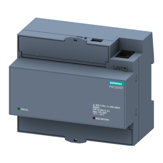
Description Features The PAC3200T is a measuring device for measuring the basic electrical variables in low- voltage power distribution. The device is capable of single-phase, two-phase, or three-phase measurement and can be used in three- or four-wire TN, TT and IT networks. The PAC3200T is mounted on a DIN rail. - Page 12 Description 3.1 Features Interfaces ● Ethernet interface ● Digital Input ● Digital output A description of the inputs and outputs can be found in section "Digital inputs and outputs (Page 17). Security ● Hardware write protection ● Password protection ● Modbus TCP port configurable ●...
-
Page 13: Measuring Inputs
Description 3.2 Measuring inputs Measuring inputs Current measurement NOTICE AC current measurement only The device is not suitable for measuring DC current. PAC3200T is designed for: ● Measuring current of 5 A for connecting standard current transformers. Each current measuring input can take a continuous load of 10 A. A momentary overcurrent of up to 100 A and a duration of 1 s is possible. - Page 14 Description 3.2 Measuring inputs Connection types Five connection types have been provided. The device can measure in single-phase, two- phase, or three-phase mode and can be used in three- or four-wire TN, TT and IT networks. Table 3- 1 Available connection types Short code Connection type 3P4W (factory setting)
- Page 15 Description 3.2 Measuring inputs Connection type 3P4W 3P3W 3P4WB 3P3WB 1P2W Measured variable Current L ✓ ✓ Average current L ✓ ✓ Apparent power L ✓ ✓ ✓ Apparent power L ✓ Apparent power L ✓ Active power L ✓ ✓...
-
Page 16: Power Demands And Counters
Description 3.3 Power demands and counters Power demands and counters 3.3.1 Acquisition of power demand Values that can be read out PAC3200T supplies the power demand of the last completed measuring period: ● Mean values for active power and reactive power, separated in each case for import and export ●... -
Page 17: Energy Counters
Description 3.4 Digital inputs and outputs 3.3.2 Energy counters Energy counters Available energy counters of the PAC3200T: ● Active energy import and export L1, L2, L3, Σ for two tariffs each ● Reactive energy import and export L1, L2, L3, Σ for two tariffs each ●... -
Page 18: Digital Output
Description 3.4 Digital inputs and outputs External voltage power supply, max. 30 V, typically 24 V Input electronics Figure 3-1 Block diagram: Digital inputs 3.4.2 Digital output Functions The following functions can be assigned to the digital output: ● No function, output is not used (default setting) ●... - Page 19 Description 3.4 Digital inputs and outputs Pulse length, turn-off time Pulse length Turn-off time Figure 3-3 Pulse length and turn-off time ● Pulse length: Time for which the signal at the digital output is "high". The minimum pulse length is 30 ms and the maximum 500 ms.
-
Page 20: Communication
Description 3.5 Communication Communication The device is equipped with the Ethernet interface. The Ethernet interface facilitates communication via the following protocols: ● Modbus TCP Protocol can be used for reading out the measured values and device configuration. ● Web server (HTTP) Protocol can only be used for reading out the measured values. -
Page 21: Mounting
Mounting WARNING The use of damaged devices may result in death, serious injury, or property damage. Do not install or start up damaged devices. Installation location The PAC3200T device is mounted on a TH35 rail (complying with EN 60715) and is intended for installation in permanently installed systems within closed rooms. -
Page 22: Installation Steps
Mounting 4.1 Installation steps Installation steps Proceed as follows to install the PAC3200T on the DIN rail: Procedure Deinstallation Tools You require the following tools to uninstall the device: ● Slotted screwdriver Procedure PAC3200T Manual, 04/2017, L1V30415168B-01... -
Page 23: Connection
Connection Safety notes Notes DANGER Hazardous Voltage Failure to observe this notice will cause death, serious injury or property damage. Turn off and lock out all power supplying this device before working on it. Note Some of the following tasks are carried out when hazardous voltage is present. For this reason, they must only be carried out by qualified personnel who are familiar with and follow the safety regulations and precautions. -
Page 24: Connections
Connection 5.2 Connections See also Safety notes (Page 9) Applying the supply voltage (Page 36) Measuring inputs (Page 13) Connections Terminal labeling Figure 5-1 Terminal labeling with screw terminals Terminal Function ↑k Current I , input ° IL1 l↓ Current I , output ↑k Current I... -
Page 25: Connection Examples
Connection 5.3 Connection examples Terminal Function (12) AC: Connection of neutral conductor DC: Connection - (13) Ethernet (14) Digital Input (15) Digital output Connection examples Some connection examples for the following types of connection are listed below: ● 3P4W - 3 phases, 4 conductors ●... - Page 26 Connection 5.3 Connection examples Connection examples (1) Three-phase measurement, four conductors, unbalanced load, without voltage transformer, with three current transformers Connection type 3P4W Fuses must be provided by the customer. for V : 10 A • for L/+: 1 A •...
- Page 27 Connection 5.3 Connection examples (2) Three-phase measurement, four conductors, unbalanced load, with voltage transformer, with three current transformers Connection type 3P4W Fuses must be provided by the customer. for V : 10 A • for L/+: 1 A • Connection of supply voltage Grounding optional Figure 5-3 Connection type 3P4W, with voltage transformer, with three current transformers...
- Page 28 Connection 5.3 Connection examples (4) Three-phase measurement, four conductors, balanced load, with voltage transformer, with one current transformer Connection type 3P4WB Fuses must be provided by the customer. for V : 10 A • for L/+: 1 A • Connection of supply voltage Grounding optional Figure 5-5 Connection type 3P4WB, with voltage transformer, with one current transformer...
- Page 29 Connection 5.3 Connection examples (6) Three-phase measurement, three conductors, unbalanced load, with voltage transformer, with three current transformers Connection type 3P3W Fuses must be provided by the customer. for V : 10 A • for L/+: 1 A • Connection of supply voltage Grounding optional Figure 5-7 Connection type 3P3W, with voltage transformer, with three current transformers...
- Page 30 Connection 5.3 Connection examples (8) Three-phase measurement, three conductors, unbalanced load, with voltage transformer, with two current transformers Connection type 3P3W Fuses must be provided by the customer. for V : 10 A • for L/+: 1 A • Connection of supply voltage Grounding optional Figure 5-9 Connection type 3P3W, with voltage transformer, with two current transformers...
- Page 31 Connection 5.3 Connection examples (10) Three-phase measurement, three conductors, balanced load, with voltage transformer, with one current transformer Connection type 3P3WB Fuses must be provided by the customer. for V : 10 A • for L/+: 1 A • Connection of supply voltage Grounding optional Figure 5-11 Connection type 3P3WB, with voltage transformer, with one current transformer...
- Page 32 Connection 5.3 Connection examples (12) Single-phase measurement, two conductors, without voltage transformer, with one current transformer Connection type 1P2W Fuses must be provided by the customer. for V : 10 A • for L/+: 1 A • Connection of supply voltage Grounding optional Figure 5-13 Connection type 1P2W, without voltage transformer, with one current transformer...
-
Page 33: Grounding Of The Ethernet Cable
Connection 5.4 Grounding of the Ethernet cable Grounding of the Ethernet cable When using industrial LAN cables, corresponding strain relief must be provided. NOTICE The upper limit values will be violated if the cable is not grounded. Compliance with the technical limit values for noise radiation and noise immunity is only guaranteed if the cable is correctly grounded. -
Page 35: Commissioning
Commissioning Overview Prerequisites ● The device has been installed. ● The device has been connected in accordance with the possible connection methods. ● Ethernet connection has been established. Steps for starting up the device 1. Apply the supply voltage 2. Parameterize the device using the SENTRON powerconfig software 3. -
Page 36: Applying The Supply Voltage
Commissioning 6.2 Applying the supply voltage Applying the supply voltage A supply voltage is required to operate the device. Please consult the technical data or the type plate for the type and level of the possible supply voltage. Refer also to the diagram Connections (Page 24) WARNING Do not apply voltage in excess of the rated voltage limit. -
Page 37: Parameterizing The Device
V3.7) via the Ethernet interface. You can download the SENTRON powerconfig configuration software from the Industry Online Support Website (https://support.industry.siemens.com/cs/document/63452759/update-version-powerconfig- v3-5?dti=0&lc=en-WW). Information and notes on the operation of SENTRON powerconfig can be found in the Online Help of the configuration software or by contacting Technical Support. -
Page 38: Setting Basic Parameters With Sentron Powerconfig
Commissioning 6.3 Parameterizing the device 6.3.1 Setting basic parameters with SENTRON powerconfig 6.3.1.1 Establish connection to the device (via Ethernet) In order to establish a connection to the PAC3200T, proceed as follows: 1. Connect the device to the PC or network via the Ethernet interface. 2. -
Page 39: Setting Basic Parameters
Commissioning 6.3 Parameterizing the device 6.3.1.2 Setting basic parameters Basic parameters are all those settings concerning the measuring inputs. "Connection type" parameter The "Connection type" parameter limits the total number of measured variables. The input circuit of the device must correspond to the parameterized connection type. Inform the device of the connection type used by entering the connection type code in the device settings. -
Page 40: Transferring The Parameters To The Device
Commissioning 6.3 Parameterizing the device "Current Input" parameter The "Current input" parameter specifies the values for the current input. When measuring using current transformers, the device must know the current conversion ratio. For this purpose, the primary and secondary current must be specified in the fields "PRIMARY CURRENT"... -
Page 41: Further Parameters
Commissioning 6.3 Parameterizing the device 6.3.1.4 Further parameters "Password protection" and "Hardware write protection" parameters Using the two parameters "Password protection" and "Hardware write protection", you can protect against write access to the device settings of the PAC3200T by means of a password. - Page 42 Commissioning 6.3 Parameterizing the device "Limits" parameter With the "Limits" parameter the monitoring of up to 6 limit values (Limit 0 to Limit 5) can be set. The "Result Logic Array" limit value comprises limits 0 to 5. The following settings can be made for each limit value. MONITORING Limit monitoring setting Yes: Limit value is monitored...
- Page 43 Commissioning 6.3 Parameterizing the device Figure 6-1 Effect of delay and hysteresis in case of limit violation PAC3200T Manual, 04/2017, L1V30415168B-01...
- Page 44 Commissioning 6.3 Parameterizing the device "Result Logic Array" parameter The device can be used to monitor the violation of up to 6 limit values. If a limit value is violated, specific actions can be triggered. In addition, the limit values can be combined with each other using a logic operation.
- Page 45 Commissioning 6.3 Parameterizing the device "Universal Counter" parameter The "Universal Counter" parameter is a configurable counter. It shows the source from which status changes or limit violations are counted: ● "Digital input" - Status changes at the digital input are counted. ●...
- Page 46 Commissioning 6.3 Parameterizing the device USAGE TYPE Usage type of the digital input. Not used: Digital input is deactivated. Count input pulses: Counting of input pulses. Note: The universal counter must also be parameterized for pulse counting. Set the parameter "Ad- vanced >...
- Page 47 Commissioning 6.3 Parameterizing the device "Digital output" parameter The following functions can be assigned to the "Digital output" parameter: ● Energy pulse output; can be programmed for active or reactive energy pulses ● Indication of the direction of rotation ● Operating state display of the device ●...
- Page 48 Commissioning 6.3 Parameterizing the device PULSES PER UNIT Number of pulses, energy unit (kWh/kvarh), that are exported. Range: 1 to 4000 Default setting: 1 The "PULSES PER UNIT" property is only visible if "Energy pulse" is set for the "USAGE TYPE". OUTPUT PULSE DIVIDER Range: 1;...
- Page 49 Commissioning 6.3 Parameterizing the device Further "Current Input" parameters The extended "Current Input" parameters are detailed below. The basic parameters are described in the section titled Setting basic parameters (Page 39). MINIMUM Shows as of which percentage of the upper measuring range CURRENT limit the current measurement is to be taken.
-
Page 51: Operation
Operation Device interface 7.1.1 Displays and operator controls The front of the PAC3200T contains the following displays and operator elements. Software button LED for Ethernet: Link / Activity LED is illuminated: Data connection available • LED flashes: Data is being transferred •... - Page 52 Operation 7.1 Device interface SENTRON powermanager Using the SENTRON powermanager energy management software energy data of the PAC3200T power monitoring device can be acquired, monitored, evaluated, displayed and archived. SENTRON powermanager offers the following functions for this purpose: ● Tree view of the customer's system (project tree) ●...
-
Page 53: Service And Maintenance
Service and maintenance Calibration The device has been calibrated by the manufacturer before shipping. Recalibration is not required provided the environmental conditions are maintained. Firmware updates The PAC3200T supports firmware updates. When updating, always use the latest version of the powerconfig configuration software. For update instructions, please see the related documentation and the online help for the configuration software. -
Page 54: Troubleshooting Guide
Service and maintenance 8.3 Troubleshooting guide Troubleshooting guide Remedies for the resolution of faults Fault Remedies Device is not working Check power supply • Check supply voltage • Check fuse • Voltage or current measured values are not displayed Check fuse •... -
Page 55: Warranty
Procedure Note Loss of warranty If you open the device, you will invalidate the Siemens warranty. Return faulty or damaged devices to Siemens. If the device is faulty or damaged, proceed as follows (only during the warranty period): 1. Remove the device; refer to section Deinstallation (Page 22). -
Page 57: Technical Data
Technical data Technical data Device configuration ● 1 optically isolated digital input ● 1 optically isolated digital output ● 1 Ethernet interface for connecting to the PC or network Measurement Only for connection to AC voltage systems Measuring method For voltage measurement True root-mean-square measurement (TRMS) For current measurement True root-mean-square measurement (TRMS) - Page 58 Technical data 9.1 Technical data Measuring inputs Impulse withstand voltage 6.5 kV (1.2/50 μs) Measuring category (acc. to IEC 61010-2-030) Input voltage V CAT III Input resistance (L-N) 1 MΩ Max. power consumption per phase 80 mW Measuring inputs for current Only for connection to AC power systems via external current transformers.
- Page 59 Technical data 9.1 Technical data Power supply Power supply Design of the power supply Wide range AC / DC power supply Work area 110 V - 250 V ±10 % Power consumption 5 VA Overvoltage category CAT III Digital Input Digital Input Number Type...
- Page 60 Technical data 9.1 Technical data Communication Ethernet interface Ethernet Modbus TCP; web server (HTTP); SNTP; DHCP Ethernet connection RJ-45 Data rate 10/100 Mbit/s Connection elements Current, voltage and supply connection Conductor cross section Rigid 0.2 ... 6 mm Flexible 0.2 ... 4 mm Flexible with end sleeve, without plastic 0.2 ...
- Page 61 Technical data 9.1 Technical data Communication ports Conductor cross section Rigid 0.14 ... 1.5 mm Flexible 0.14 ... 1.5 mm Flexible with end sleeve, without plastic 0.25 ... 1 mm sleeve Flexible with end sleeve and plastic 0.25 ... 1.5 mm sleeve 26 ...
- Page 62 Technical data 9.1 Technical data Environmental conditions Operation is only permissible inside an enclosed dry room. Environmental conditions Temperature range Ambient temperature during operating -25 °C … +55 °C (K55) phase Ambient temperature during transport -25 °C … +70 °C and storage Relative humidity 0 to 75% RH...
- Page 63 Approvals The PAC3200T complies with the requirements of the European Directives. CE conformity The SENTRON PAC3200T complies with the requirements of the following European Directives: DIRECTIVE 2014/30/EU OF THE EUROPEAN PARLIAMENT AND COUNCIL of February 26, 2014, on the harmonization of the...
-
Page 64: Labeling
Technical data 9.2 Labeling Labeling Labels on the housing of the PAC3200T Symbol, label Explanation PAC3200T Product designation LQN/YYMMDDxxxxx Serial number of the device EAC certification Risk of electric shock General Warning Symbol Overvoltage category CAT III for current and voltage inputs Protective insulation, device with protection class II (10) CE mark. -
Page 65: Dimension Drawings
Dimension drawings Note: All dimensions in mm. Frame dimensions Figure 10-1 Frame dimensions PAC3200T Manual, 04/2017, L1V30415168B-01... -
Page 67: Appendix
Appendix Modbus TCP Detailed information about Modbus TCP can be found on the Modbus website (http://www.modbus.org). A.1.1 Function codes Function codes control the data exchange. In doing so, a function code tells the slave which action it is to take. If an error occurs, the most significant bit (MSB) is set in the FC byte of the response frame. -
Page 68: Modubs Exception Codes
Appendix A.1 Modbus TCP A.1.2 Modubs exception codes Overview Table A- 2 Modubs exception codes Exception codes Name Meaning Remedy Illegal Func- Illegal function: Check which function tion codes are supported. The function code in the re- • quest is not a permissible ac- tion for the slave. -
Page 69: Modbus Measured Variables With The Function Codes 0X03 And 0X04
Appendix A.1 Modbus TCP A.1.3 Modbus measured variables with the function codes 0x03 and 0x04 Addressing the measured variables You can use the Modbus function codes 0x03 and 0x04 on all the measured variables listed below. Note Error in the case of inconsistent access to measured values. Please ensure the start offset of the register is correct when making read accesses. - Page 70 Appendix A.1 Modbus TCP Offset Number of Name Format Unit Value range Access registers Reactive power L3 Float Power factor L1 Float 0 ... 1 Power factor L2 Float 0 ... 1 Power factor L3 Float 0 ... 1 THD-R voltage L1 Float 0 ...
- Page 71 Appendix A.1 Modbus TCP Offset Number of Name Format Unit Value range Access registers Max. THD-R voltage L1 Float 0 ... 100 Max. THD-R voltage L2 Float 0 ... 100 Max. THD-R voltage L3 Float 0 ... 100 Max. THD-R current L1 Float 0 ...
- Page 72 Appendix A.1 Modbus TCP Offset Number of Name Format Unit Value range Access registers Min. Total Reactive Power Float Min. total power factor Float Limit violations * Unsigned long Byte 3 Bit 0 = Limit 0 Device diagnostics and device status * Unsigned long Byte 0 system status...
- Page 73 Appendix A.1 Modbus TCP Offset Number of Name Format Unit Value range Access registers Apparent energy tariff 1 Double Overflow 1.0e+12 Apparent energy tariff 2 Double Overflow 1.0e+12 L1 active energy import tariff 1 Double Overflow 1.0e+12 L1 active energy import tariff 2 Double Overflow 1.0e+12 L1 active energy export tariff 1...
-
Page 74: Structure - Digital Input Status And Digital Output Status With The Function Codes 0X03 And 0X04
Appendix A.1 Modbus TCP A.1.4 Structure - Digital input status and digital output status with the function codes 0x03 and 0x04 The following are available via Modbus: ● "Status of the digital input" ● "Status of the digital output" Input status and output status of the PAC3200T Table A- 4 Structure - Status of the digital inputs and outputs, Modbus offset 207 and 209 Name... -
Page 75: Modbus Status Parameters With The Function Code 0X02
Appendix A.1 Modbus TCP A.1.6 Modbus status parameters with the function code 0x02 Status parameters You can use the Modbus function code 0x02 on all the status parameters listed below. Table A- 6 Status parameters Offset Number of Name Format Value range Access registers... -
Page 76: Modbus Settings With The Function Codes 0X03, 0X04 And 0X10
Appendix A.1 Modbus TCP A.1.7 Modbus settings with the function codes 0x03, 0x04 and 0x10 Addressing the settings You can use the Modbus function codes 0x03 and 0x04 for read accesses and 0x10 for write accesses on all the settings parameters listed below. Table A- 7 Settings parameters Offset... - Page 77 Appendix A.1 Modbus TCP Table A- 8 Settings parameter for the digital input Offset Number of Name Unit Format Value range Access registers 50025 Digital input "Action" unsigned long Status only Pulse input High tariff / low tariff switching Synchronization 50029 "Pulse input"...
- Page 78 Appendix A.1 Modbus TCP Offset Number of Name Unit Format Value range Access registers 50147 Digital output timeout unsigned long 0.1 ... 18000 50237 Output pulse divider unsigned long 1 kWh 10 kWh 100 kWh 1000 kWh Table A- 10 Settings parameters for the universal counter source Offset Number of...
- Page 79 Appendix A.1 Modbus TCP Offset Number of Name Unit Format Value range Access registers 50071 Source unsigned long V_L1 V_L2 V_L3 V_L12 V_L23 V_L31 I_L1 I_L2 I_L3 VA_L1 10 = VA_L2 11 = VA_L3 12 = P_L1 13 = P_L2 14 = P_L3 15 =...
- Page 80 Appendix A.1 Modbus TCP Offset Number of Name Unit Format Value range Access registers 41 = V_BAL 42 = I_BAL 43 = V_PHASE_BAL 44 = 50073 Value float 50075 Mode ≥ / < unsigned long Greater than Less than Table A- 12 Setting parameter for limit 1 Offset Number of...
- Page 81 Appendix A.1 Modbus TCP Table A- 14 Setting parameter for limit 3 Offset Number of Name Unit Format Value range Access registers 50105 ON/OFF unsigned long See value range table "Setting parameters for 50107 Hysteresis float limit 0" 50109 Delay unsigned long 50111 Operation in Limit Logic...
-
Page 82: Modbus Communication Parameters With The Function Codes 0X03, 0X04 And 0X10
Appendix A.1 Modbus TCP A.1.8 Modbus communication parameters with the function codes 0x03, 0x04 and 0x10 Addressing the communication parameters Table A- 17 Communication parameters Offset Number of Name Unit Format Applicable Value range Access registers Modbus func- tion codes 62997 Subnet Firewall unsigned long... -
Page 83: Modbus Device Information With The Function Codes 0X03, 0X04 And 0X10
3A00 ... F6FF [64025] Specific Profile ID unsigned short [64026] Version of the I&M data 2 unsigned char 0.0 ... 255.255 [64027] Supported I&M data unsigned short 00 ... FF *) 42 stands for Siemens AG PAC3200T Manual, 04/2017, L1V30415168B-01... - Page 84 Appendix A.1 Modbus TCP Table A- 19 I&M 1-4 parameters with the function codes 0x03, 0x04 and 0x10 Offset Total regis- Number of reg- Name Format Value range Access ters isters per pa- rameter Start offset [16] Plant identifier Char 32 ASCII 64028 [64044]...
-
Page 85: Modbus Command Parameters
Appendix A.1 Modbus TCP A.1.10 Modbus command parameters Addressing the command parameters You can apply the Modbus function code 0x06 to the command parameters. Table A- 20 Command parameters Offset Number Name Unit Format Value range Access of regis- ters 60000 Reset the device to the unsigned short... -
Page 86: Modbus Standard Device Identification With The Function Code 0X02
Appendix A.1 Modbus TCP Offset Number Name Unit Format Value range Access of regis- ters 60008 Switching outputs unsigned short 0ffh ... 1ffh (if parameterized) Byte 0 Digital output 0.0 Byte 1 Byte 1 60009 Switching command for unsigned short High 0 ... -
Page 87: Index
Index Approvals, 63 Energy counters, 17 Environmental conditions, 62 Error code, 69, 83 Exception code, 68 Basic settings Parameterizing, 39 Bit mask, 74 Features, 11 Firmware updates, 53 Frame dimensions, 65 Function code, 67, 86 CE conformity, 63 Command parameters, 85 Communication, 60 Communication parameters, 82 Components of the product, 7... - Page 88 Index Mounting Procedure, 22 Screw terminal, 60 Mounting dimensions, 65 Security, 12 Startup, 35 Parameterizing the device, 37 Prerequisites, 35 Object ID, 86 Status parameters, 75 Offset, 68, 69, 74, 76, 77, 78, 78, 80, 80, 81, 85 Storage, 21 Panel cutout Technical data, 57 Dimensions, 65...
- Page 90 Further Information Always at your disposal: our extensive support www.siemens.com/online-support Siemens AG Energy Management Low Voltage & Products Postfach 10 09 53 93009 REGENSBURG Germany Subject to change. 3ZW1012-7KM32-0AB1 © Siemens AG 2017 EM LP Online...
Need help?
Do you have a question about the SENTRON PAC3200T and is the answer not in the manual?
Questions and answers