Table of Contents
Advertisement
Quick Links
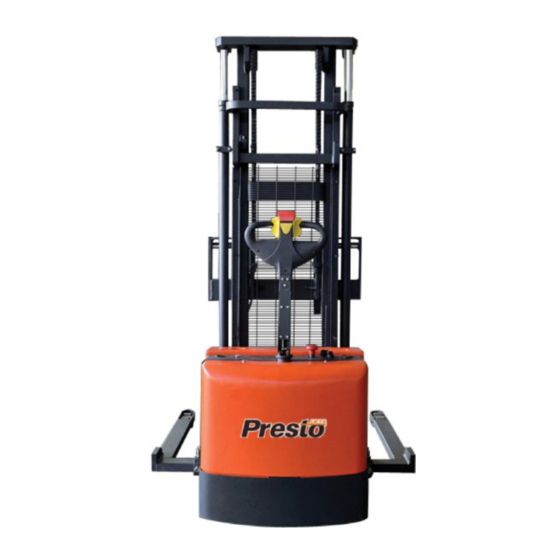
Power Stak
PPS3000-125AS
This manual covers PowerStak units with frame numbers
starting with GC stamped into the mast and shipped March
2014 and after.
Installation, Operation
and Service Manual
Model Number _____________________________________
Serial # ____________________________________________
Date Placed in Service _____________
IMPORTANT: READ CAREFULLY
BEFORE INSTALLING OR OPERATING LIFT
MARCH 2015
Advertisement
Table of Contents
Troubleshooting

Subscribe to Our Youtube Channel
Related Manuals for Presto Lifts Power Stak PPS3000-125AS


Summary of Contents for Presto Lifts Power Stak PPS3000-125AS
- Page 1 Power Stak PPS3000-125AS This manual covers PowerStak units with frame numbers starting with GC stamped into the mast and shipped March 2014 and after. Installation, Operation and Service Manual Model Number _____________________________________ Serial # ____________________________________________ Date Placed in Service _____________ IMPORTANT: READ CAREFULLY BEFORE INSTALLING OR OPERATING LIFT MARCH 2015...
-
Page 2: Limited Warranty
There are no implied warranties of any kind, more specifically; there are no warranties of merchant- ability or fitness for any particular purpose. Presto Lifts’ sole warranty shall be as set forth in this limited warranty. Presto Lifts will elect to repair or replace a defective component without charge, if any components should become defective within the limited warranty period. -
Page 3: Table Of Contents
TABLE OF CONTENTS S E C T I O N 1: Limited Warranty ..............................2 Wheel Traction and Straddle Leg Set-Up ......................4 Introduction .................................5 Responsibility of Owners and Users ........................6 S E C T I O N 2: Certified Operator Training ..........................7 Safety .................................7 S E C T I O N 3: Installation ................................9... -
Page 4: Wheel Traction And Straddle Leg Set-Up
Drive Wheel traction performance may be affected; If traction issues are encoun- tered Rubber Drive Wheels are available through special order. Please contact Customer Service at Presto Lifts 1-800-343-9322 When any PowerStak is operated on a wet, oily, powdery, sandy or non-uniform liquid or granular surface Drive Wheel traction performance will be affected and loss of traction will occur. -
Page 5: Introduction
INTRODUCTION This manual attempts to provide all of the information necessary for the safe and proper installation, operation and maintenance of Presto Lifts Inc. battery operated, Power Stak. It is important that all personnel involved with the installation, maintenance or operator of the stacker read this manual. -
Page 6: Responsibility Of Owners And Users
Responsibility of Owners and Users Inspection and Maintenance The device shall be inspected and maintained in proper working order in accordance with Presto’s owner’s manual. Removal from Service Any device not in safe operating condition such as, but not limited to, excessive leakage, missing rollers, pins, or fasteners, any bent or cracked structural members, cut or frayed electric, hydraulic, or pneumatic lines, damaged or malfunctioning controls or safety devices, etc. -
Page 7: Certified Operator Training
(OSHA 1910.178 29QFR-7-1-06 Edition) Presto lifts does not offer operator training. Operator training programs may be offered by your local Presto Lifts dealer or obtained online. Enter, "powered industrial truck operator training" into a search engine. - Page 8 The battery operated stackers are very powerful lifts direction of travel. Keep your feet clear of the capable of doing large amounts of work. stacker. • Keep the stacker under control at all times. DO NOT OPERATE THESE LIFTS WITHOUT Operate at a speed that allows you to stop safely.
-
Page 9: Installation
For travel speed adjustment, please contact • Check for signs of damage especially to the customer service at Presto Lifts 1-800-343-9322 back cabinet that houses the battery, electrical/ hydraulic power pack. • Check all electrical and hydraulic connec- S E C T I O N 4 tions for tightness. -
Page 10: Figure 1: Operational Buttons
the bottom boards, and if the forks project through the The operator can engage the butterfly forward with the end of the pallet, the tips of fork may go into the next right hand and engage the turtle speed button with the left hand. -
Page 11: Daily Operations Maintenance Checks
DAILY OPERATIONS to the full vertical position with the brake applied and the forks in lowered position. MAINTENANCE CHECKS: Reversing Safety: Battery At the end of the handle there is a large, red reversing A. Check for corroded and loose terminals. bar (belly button switch) that is designed to protect the A white powder substance will be present if operator from injury. -
Page 12: Suggested Daily Operator Checklist
S A F E T Y I N S T R U C T I O N S DAILY OPERATOR CHECK LIST CHARGE CONDITION/BATTERY CHECK LIST 1. Check Battery Discharge Indicator (Fuel Gage and Hour Meter) – Be sure unit is showing proper Charge Level before operating unit 2. -
Page 13: Battery Maintenance
S E C T I O N 5 DANGER Never alter the AC cord or plug provided. If it will BATTERY MAINTENANCE not fit outlet, have proper outlet installed by a quali- fied electrician. Improper connection can result in a risk of an electric shock. -
Page 14: Maintenance
MONTHLY OPERATIONS S E C T I O N 6 MAINTENANCE CHECKS: MAINTENANCE Battery (maintenance free) Operation of Presto Power Stak is very simple — as A. Clean terminals. is their construction. They require very little main- B. Clean battery compartment area if there are tenance. -
Page 15: Troubleshooting
S E C T I O N 7 TROUBLESHOOTING Before starting the troubleshooting, you have to: A. Put the truck on an even and solid surface. B. Turn off key switch or disconnect the battery ter- minals. 1. Unit will not lift (motor does not run) •... -
Page 16: Troubleshooting Check List
PROGRAMMER LCD DISPLAY CODE POSSIBLE CAUSE EFFECT OF FAULT Controller Overcurrent 1. External short of phase U,V, or W motor connections. Shutdown Motor; 2. Motor parameters are mis-tuned. Shutdown Main Contactor; 3. Controller defective. Shutdown EM Brake; 4. Speed encoder noise problems. Shutdown Throttle;... - Page 17 Controller Overtemp Cutback 1. See Monitor menu Controller: Temperature. Reduced drive and brake torque. 2. Controller is performance-limited at this temperature. 3. Controller is operating in an extreme environment. 4. Excessive load on vehicle. 5. Improper mounting of controller. Undervoltage Cutback 1.
- Page 18 Coil2 Driver Open/Short 1. Open or short on driver load. Shutdown Driver2. 2. Dirty connector pins. 3. Bad crimps or faulty wiring. EM Brake Open/Short 1. Open or short on driver load. Shutdown EM Brake; 2. Dirty connector pins. Shutdown Throttle; 3.
- Page 19 Pot Low Overcurrent 1. See Monitor menu Outputs: Pot Low. ShutdownThrottle; 2. Combined pot resistance connected to pot low is too low. Full Brake. EEPROM Failure 1. Failure to write to EEPROM memory. This can be caused by EEPROM Shutdown Motor; memory writes initiated by VCL, by the CAN bus, by adjusting parameters Shutdown Main Contactor;...
- Page 20 External Supply Out of Range 1. External load on the 5V and 12V supplies draws either too much or too None, unless a fault action is pro- little current. grammed in VCL. 2. Fault Checking Menu parameters Ext Supply Max and Ext Supply Min are mis-tuned.
- Page 21 Motor Type Fault 1. The Motor_Type parameter value is out of range. Shutdown Motor; Shutdown Main Contactor; Shutdown EM Brake; Shutdown Throttle; Full Brake; Shutdown Pump. VCL/OS Mismatch 1. The VCL software in the controller does not match the OS software in Shutdown Motor;...
-
Page 22: Stacker Body Components
Stacker Body Components Item Description Item Description Item Description Outer Mast Screw Screw Spring Washer Casing Assy Rear Cover Top Cover Bolt Spring Washer Straddle Leg, Left Hand Washer Washer Fixing Board, Charger Bolt Bolt Washer Spring Washer, Axial Auxiliary wheel Spring Washer Spindle Seat, Auxiliary Wheel... -
Page 23: Control Pod
CONTROL POD PPS2200-62NFO-27 Control Pod Control Pod Bottom Item Description Lifting Switch Lowering Switch Butterfly Switch Item Description Belly Button Stop Switch Lifting Switch Horn Button Lowering Switch Turtle Speed Switch Running Switch Emergency Reverse Switch Horn Button PRESTO OWNER’S MANUAL Page 23 POWER STAK... -
Page 24: Suspension Assembly
Suspension Assembly Item Description Qty Item Description Item Description Drive Wheel Assembly Bolt Micro Switch Spindle Baffle Ring Screw Spindle Copper Bushing Pivot Pin Bushing Bracket Assembly, Suspension Snap Ring Cushion Screw Bushing Spring Cover, Steering Arm Screw Cover, Spindle Screw Washer Air Spring... -
Page 25: Drive Unit Assembly
Drive Unit Assembly Item Description Item Description Item Description Screw Screw Washer Cover Electromagnetic Plug Bearing Screw Plate Screw Helical Gear Axis Friction Disk Connecting Flange Bearing Friction Cover Baffle Ring Three Jaw Gear Framework Seal Motor Helical Gear Axis Shaft, Steering Wheel Speed Sensor Bearing... -
Page 26: Carriage Assembly
Carriage Assembly Item Description Fork Snap Ring Bolt Roller, Main Screw Spring Washer Side Roller Washer Spacer Load Bracket Assembly Feed Shaft PRESTO OWNER’S MANUAL Page 26 POWER STAK... -
Page 27: Mast Assembly
Mast Assembly Item Description Item Description Qty Item Description Bolt Wheel, Chain Adaptor Spring Washer U Bolt Screw Washer Seat, Limit Switch Outer Mast Inner Mast Washer Screw Spacer Spring Washer Washer Main Roller Screw Net Cover Side Roller Micro Switch Washer Spring Washer Cylinder... -
Page 28: Lift Cylinder Assembly
Lift Cylinder Assembly Item Description Lift Cylinder Piston Rod Baffle Ring Ring, Back Up Plug Cylinder Block Ring U-Seal Ring, Dust PRESTO OWNER’S MANUAL Page 28 POWER STAK... -
Page 29: Hydraulic Power Unit Assembly
Hydraulic Power Unit Assembly Item Description Item Description Item Description Valve Block Coupling Oil Filter Relief Valve Motor Tank, Plastic Unilateral Valve Switch Bolt with Spring Washer Throttle Valve O-Ring Solenoid Valve Gear Pump Cover, Oil Tank Screw Plug, Metal Bolt with Spring Washer Clamp Screw Plug, Plastic... -
Page 30: Hydraulic System Assembly
Hydraulic System Assembly Item Description Bolt Spring Washer Washer Hydraulic Assembly Oil Hose O-Ring L-Adaptor PRESTO OWNER’S MANUAL Page 30 POWER STAK... -
Page 31: Hydraulic Schematic
PRESTO OWNER’S MANUAL Page 31 POWER STAK PPS3000-125AS... -
Page 32: Electrical Diagrams
PRESTO OWNER’S MANUAL Page 32 POWER STAK PPS3000-125AS... - Page 33 PRESTO OWNER’S MANUAL Page 33 POWER STAK PPS3000-125AS...
-
Page 34: Label Placement
PRESTO OWNER’S MANUAL Page 34 POWER STAK PPS3000-125AS... -
Page 35: Ordering Replacement Parts
ORDERING REPLACEMENT PARTS Presto Lifts has carefully chosen the components in your unit to be the best available for the purpose. Replacement parts should be identical to the original equipment. Presto Lifts will not be responsible for equipment failures resulting from the use of incorrect replacement parts or from unauthorized modifications to the unit. -
Page 36: Restocking Policy
The customer should inspect to ensure it is not received damaged, has no concealed damage or is not incomplete. Parts orders are determined to be complete based upon Presto Lift, Inc. inspection sheets and carrier shipping weights. PRESTO OWNER’S MANUAL Page 36 POWER STAK PPS3000-125AS... - Page 37 MANY NEEDS REQUIRE MANY OPTIONS... LET PRESTO MEET THOSE NEEDS! Call Presto Sales for stock or customized lift inquiries: 800-343-9322 Email: sales@prestolifts.com...
Need help?
Do you have a question about the Power Stak PPS3000-125AS and is the answer not in the manual?
Questions and answers