Advertisement
Quick Links
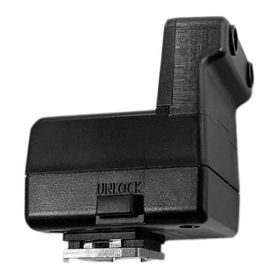
26306
Mini Flash Trigger for Olympus
(Compatible with NA-EM1/EM5II)
Instruction Manual
F
OREWORD
Thank you for your purchase of a NAUTICAM product.
At NAUTICAM, we pride ourselves in the ability to recognize the requirements
of professional as well as amateur underwater photographers and fulfill them
through the innovative designs of our products. We strive to achieve a high
level of user-friendliness by allowing stress-free installation and easy
operation of all important functions of the camera.
Please read this manual carefully before using the product, this will maximize
its performance as well as its lifetime.
W
ARRANTY
All NAUTICAM Products are warranted against any material and
manufacturing defects for two years from the date of purchase for consumer
use. This warranty only applies to products purchased from authorized
NAUTICAM dealers and does not extend beyond the original retail purchaser.
To return your product for service, please contact your regional authorized
service center(s). Please note that this warranty only applies when the product
is purchased in the territory where the service center is located.
NAUTICAM does not hold responsibility for damage, of any nature, to any
equipment used with and/or placed within our products.
NAUTICAM accepts no liability for any loss of captured images or the inability
to capture images even if it is due to the malfunctioning of our products.
Unauthorized modifications and/or repairs of our products will automatically
invalidate the warranty.
P
RECAUTIONS
• Use only batteries approved for use in this product, do not mix old and new
batteries.
• Check the battery terminals before installing into the product.
• Remove batteries for storage, do not store the product in an environment
of high humidity.
• Do not leave the product in direct sunlight for prolonged periods.
• Keep out of reach of children, failure to do so could result in injury.
• Defective products should be shipped to our distributors for service,
unauthorized disassembling and/or modifications could result in mal-
function.
I
P
DENTIFICATION OF
ARTS
LED modules attachment socket
Battery compartment cover
Indicator
On/off switch
EM1 holder
EM1 LED module
Hotshoe connector
Release button
EM5II holder
EM5II LED module
LED M
I
ODULE
NSTALLATION
Choose the required LED module and attach it to the flash trigger base with
the LEDs facing outwards. Make sure the connector on the bottom of the LED
module correctly plug-in to the socket on the flash trigger base.
Secure the LED module by tightening the two supplied screws at the bottom
of the flash trigger.
B
I
ATTERIES
NSTALLATION
Press
Slide
Make sure the On/Off switch is in the OFF position. Remove the battery
compartment cover by sliding it outwards.
Install the batteries (CR2450 x2pcs) with +ve terminal facing up as shown
above. Close the battery compartment cover and then switch the trigger unit
on. The indicator will turn green.
Indicator
Green light
Flashing Green light
(1 flash/sec)
Flashing Red light
(1 flash/sec)
H
P
OUSING
REPARATION
NA-EM1
Screws
Replace the holder as indicated above with the supplied new holder. Remove
the two screws to detach it.
For NA-EM5II, remove the inner part of the flash on/off lever.
NA-EM5II
C-clip
In the rear housing of NA-EM5II, locate the flash on/off inner mechanism (on
top of the viewfinder) and then remove the c-clip as indicated above. Detach
the flash on/off inner part and spring from the shaft.
Tip: To remove the c-clip, insert a
nail or a small flat head screwdriver
into the gap as shown below, then
pull it out.
Attention: Keep these parts for
restoring to use with internal flash.
--- continue on next page ---
Status of flash trigger
Start up.
Ready to use, normal
operation.
Low battery warning,
replace batteries.
NA-EM5II
Screws
NA-EM5II
Spring
Inner part
Advertisement

Related Manuals for Nauticam 26306


Summary of Contents for Nauticam 26306
- Page 1 Close the battery compartment cover and then switch the trigger unit equipment used with and/or placed within our products. on. The indicator will turn green. NAUTICAM accepts no liability for any loss of captured images or the inability Indicator Status of flash trigger to capture images even if it is due to the malfunctioning of our products.
- Page 2 --- continued from front page --- To restore, align the inner part to the shaft with the extruded part on the left hand side and install the spring and inner part back to the shaft. Then push the c-clip to the groove on the shaft with a pliers or similar to secure. Attention: Extra c-clips are provided in the package, DO NOT reuse the c-clip.