Sign In
Upload
Manuals
Brands
Precision Digital Corporation Manuals
Measuring Instruments
PROVU PD7000
Precision Digital Corporation PROVU PD7000 Manuals
Manuals and User Guides for Precision Digital Corporation PROVU PD7000. We have
1
Precision Digital Corporation PROVU PD7000 manual available for free PDF download: Instruction Manual
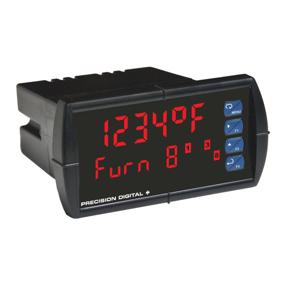
Precision Digital Corporation PROVU PD7000 Instruction Manual (48 pages)
Temperature Meter, PROVU Series
Brand:
Precision Digital Corporation
| Category:
Measuring Instruments
| Size: 2 MB
Table of Contents
Table of Contents
3
Table of Figures
4
Introduction
4
Ordering Information
5
Specifications
5
General
5
Temperature Input
6
Relays
6
Isolated 4-20 Ma Output
7
Modbus ® RTU Serial Communications
7
PDA1044 Digital Input & Output Expansion Module
7
Meterview Pro
7
Compliance Information
8
Safety
8
Electromagnetic Compatibility
8
Safety Information
9
Installation
9
Unpacking
9
Panel Mounting Instructions
10
Mounting Dimensions
10
Figure 1. 1/8 DIN Panel Cutout Dimensions
10
Figure 2. Panel Mounting Details
10
Figure 3. Meter Dimensions - Side View
10
Figure 4. Meter Dimensions - Top View
10
Connections
11
Connectors Labeling
11
Power Connections
11
Figure 5. Connector Labeling for Fully Loaded
11
Figure 6. Power Connections
11
Signal Connections
12
Figure 7. Thermocouple Input Connections
12
Figure 8. Three-Wire RTD Input Connections
12
Figure 9. Two-Wire RTD Input Connections
12
Figure 10. Four-Wire RTD Input Connections
12
Connections for Averaging RTD Sensors
13
Modbus RTU Serial Communications
13
Relay Connections
13
Figure 11. Average Temperature RTD Input Connections
13
Figure 12. Relay Connections
13
Switching Inductive Loads
14
F4 Digital Input Connections
14
Figure 13. AC and DC Loads Protection
14
Figure 14. Low Voltage DC Loads Protection
14
Figure 15. F4 Digital Input Connections
14
4-20 Ma Output Connections
15
Power Supply for Analog Output Loop or Other Uses
15
External Relays & Digital I/O Connections
15
Figure 16. 4-20 Ma Output Connections
15
Figure 17. Expansion Modules & DIN Rail Mounting Kit
15
Figure 18. External Relays Module Connections
15
Figure 19. Digital I/O Module Connections
15
Interlock Relay Feature
16
Figure 20. Interlock Connections
16
Setup and Programming
17
Front Panel Buttons and Status LED Indicators
17
Meterview ® Pro Software
18
Meterview Pro Installation
18
Display Functions & Messages
19
Main Menu
21
Setting Numeric Values
21
Setting up the Meter (Setup)
22
Setting the Input Signal (Input)
23
Selecting the Temperature Scale (F or C)
23
Setting the Decimal Point (Dec Pt)
23
Setting the Display Parameter & Intensity (Dsplay)
23
Setting the Input Units or Custom Tags (Units)
24
Setting the Relay Operation (Relay)
24
Setting the Relay Action
25
Programming Set and Reset Points
25
Setting Fail-Safe Operation
25
Programming Time Delay
25
Relay Action for Loss of Input (Input Break)
25
Relay and Alarm Operation Diagrams
26
High Alarm Operation (Set > Reset)
26
Low Alarm Operation (Set < Reset)
26
High Alarm with Fail-Safe Operation (Set > Reset)
26
Low Alarm with Fail-Safe Operation (Set < Reset)
26
Pump Alternation Control Operation
27
Relay Sampling Operation
27
Signal Loss or Input Break Relay Operation
28
Time Delay Operation
28
Relay Operation Details
29
Overview
29
Relays Auto Initialization
29
Fail-Safe Operation
29
Front Panel Leds
29
Latching and Non-Latching Relay Operation
30
Non-Latching Relay (Auto)
30
Non-Latching Relay (A-Nman)
30
Latching Relay (Latch)
30
Latching Relay (Lt-Clr)
30
Acknowledging Relays
31
Setting up the Interlock Relay (Force On) Feature
31
Figure 21. Acknowledge Relays W/Function Key or Digital Input
31
Scaling the 4-20 Ma Analog Output (Aout)
32
Reset Menu (Reset)
32
Control Menu (Contrl)
32
Setting up the Password (Pass)
33
Protecting or Locking the Meter
33
Making Changes to a Password Protected Meter
33
Disabling Password Protection
33
Advanced Features Menu
34
Advanced Features Menu & Display Messages
34
Offset Adjust (Adjust)
35
Recalibration of the Meter (T CAL)
36
Noise Filter (Filter)
37
Noise Filter Bypass (Bypass)
37
Rounding Feature (Round)
37
Modbus RTU Serial Communications (Serial)
37
Select Menu (Select)
38
Analog Output Programming (Aoutpr)
38
Programmable Function Keys User Menu (User)
39
Internal Temperature Calibration (ICAL)
40
Meter Operation
42
Front Panel Buttons Operation
42
Function Keys Operation
42
F4 Operation
42
Maximum/Minimum Readings
43
Troubleshooting
44
Diagnostics Menu (Diag)
44
Determining Software Version
44
Reset Meter to Factory Defaults
44
Factory Defaults & User Settings
45
Troubleshooting Tips
46
EU Declaration of Conformity
47
Advertisement
Advertisement
Related Products
Precision Digital Corporation PD750
Precision Digital Corporation PD752
Precision Digital Corporation Trident PD765-6R0-00
Precision Digital Corporation Trident PD765-6R3-10
Precision Digital Corporation Trident PD765-6R5-10
Precision Digital Corporation Trident PD765-7R2-00
Precision Digital Corporation Trident PD765
Precision Digital Corporation PD765-6X0-00
Precision Digital Corporation PD765-7X0-00
Precision Digital Corporation PD765-6X0-10
Precision Digital Corporation Categories
Measuring Instruments
Controller
Cash Counter
Scanner
Racks & Stands
More Precision Digital Corporation Manuals
Login
Sign In
OR
Sign in with Facebook
Sign in with Google
Upload manual
Upload from disk
Upload from URL