Table of Contents
Advertisement
Quick Links
PLEASE NOTE!
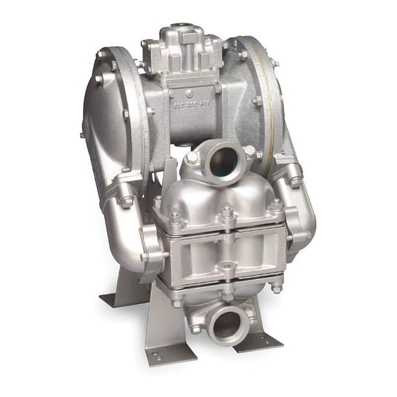
The photos shown in this manual are for general instruction only. YOUR SPECIFIC
MODEL MAY NOT BE SHOWN. Always refer to the parts list and exploded view
drawing for your specific model when installing, disasembling or servicing your pump.
PRINCIPLE OF PUMP OPERATION
This ball check valve pump is powered by compressed air and is a 1:1 pressure
ratio design. The pump is alternately pressurize through the inner side of one
diaphragm chamber, while simultaneously exhausting the other inner chamber. Air
pressure causes the diaphragms, (which are connected by a common rod,) to move
endwise. Air pressure is applied over the entire surface of the diaphragm, while liquid
is discharged from the opposite side. The diaphragm operates under a balanced
condition during the discharge stroke, and the unit can be operated at discharge
heads over 200 feet (61 meters) of water head.
The diaphragms are connected by a common rod, secured by plates to the center
of the diaphragms. One diaphragm performs the discharge stroke, while the other is
pulled to perform the suction stroke in the opposite chamber.
For maximum diaphragm life, keep the pump as close to the liquid being pumped
as possible. Positive suction head in excess of 10 feet of liquid (3.048 meters) may
require a back pressure regulating device. This will maximize diaphragm life.
Alternate pressuring and exhausting of the diaphragm chamber is performed by
means of an externally mounted, pilot operated, four-way spool type air distribution
valve. When the spool shifts to one end of the valve body, inlet air pressure is applied
to one diaphragm chamber and the other diaphragm chamber exhausts air. When the
spool shifts to the opposite end of the valve body, the porting of chambers is reversed.
The air distribution valve spool is moved by an internal pilot valve which alternately
pressurizes one side of the air distribution valve spool, while exhausting the other side.
The pilot valve is shifted at each end of the diaphragm stroke by the diaphragm plate
coming in contact with the end of the pilot spool. This pushes the pilot valve into position
for shifting of the air distribution valve.
The chambers are manifolded together with a suction and discharge check valve
for each chamber which maintains flow in one direction through the pump.
INSTALLATION & START-UP
Locate the pump as close to the product being pumped as possible. Keep suction
line length and number of fittings to a minimum. Do not reduce line size.
For installations of rigid piping, short flexible sections of hose should be installed
between pump and piping. This reduces vibration and strain to the piping system. A
Warren Rupp Tranquilizer
pulsation in flow.
This pump was tested at the factory prior to shipment and is ready for operation.
It is self-priming from a dry start for suction lifts of 20 feet (6.096 meters) or less. For
suction lifts exceeding 20 feet of liquid, fill the chambers with liquid prior to priming.
AIR SUPPLY
Air supply pressures cannot exceed 125 psi (8.61 bar). Connect the pump air inlet
to an air supply of sufficient capacity and pressure required for desired performance.
When the air line is solid piping, use a short length of flexible hose [not less than
3/4" (19mm) in diameter] between pump and piping to eliminate strain to pipes.
WARREN RUPP, INC. A Unit of IDEX Corporation • P.O. Box 1568 • Mansfield, Ohio 44901-1568 USA • (419) 524-8388 • Fax (419) 522-7867 • www.warrenrupp.com
7/05
®
surge suppressor is recommended to further reduce
SERVICE AND OPERA
SERVICE AND OPERA
SERVICE AND OPERA
SERVICE AND OPERATING MANU
SERVICE AND OPERA
I M2 c/b T5
II 2GD b T5
TING MANU
TING MANU
TING MANU
TING MANUAL
Model HDB2-A
Model HDB2-A
Model HDB2-A
Model HDB2-A
Model HDB2-A
CE
WARNING
HAZARD WARNING — POSSIBLE
EXPLOSION HAZARD can result if 1,1,1-
Trichloroethane, Methylene Chloride
or other Halogenated Hydrocarbon
solvents are used in pressurized fluid
systems having Aluminum or Galva-
nized wetted parts. Death, serious bodily
injury and/or property damage could
result. Consult with the factory if you
have questions concerning Halogenated
Hydrocarbon solvents.
IMPORTANT
Read these instructions completely,
before installation and start-up. It is the
responsibility of the purchaser to retain
this manual for reference. Failure to
comply with the recommendations
stated in this manual will damage the
pump, and void factory warranty.
WARNING
Take action to prevent static sparking.
Fire or explosion can result, especially
when handling flammable liquids. The
pump, piping, valves, containers or other
miscellaneous equipment must be
grounded. (See page 6)
BEFORE OPERATION
Before pump operation, inspect all
gasketed fasteners for looseness
caused by gasket creep. Retorque loose
fasteners to prevent leakage. Follow
recommended torques stated in the card
attached to the new pump.
Model HDB2-A Page 1 Rev B
AL
AL
AL
AL
Type 3
Advertisement
Table of Contents

Related Manuals for Sandpiper HDB2-A


Summary of Contents for Sandpiper HDB2-A
-
Page 1: Before Operation
3/4" (19mm) in diameter] between pump and piping to eliminate strain to pipes. WARREN RUPP, INC. A Unit of IDEX Corporation • P.O. Box 1568 • Mansfield, Ohio 44901-1568 USA • (419) 524-8388 • Fax (419) 522-7867 • www.warrenrupp.com 7/05 Model HDB2-A Page 1 Rev B... -
Page 2: Air Exhaust
Turn the center screw loose from the back plate and the assembly will come apart. REASSEMBLY All procedures for reassembling the pump are the reverse of the disassembly instructions with further instructions as shown: 7/05 Model HDB2-A Page 2 Rev B... - Page 3 A Note about Air Valve Lubrication The SANDPIPER pump’s pilot valve and main air valve assemblies are designed to operate WITHOUT lubrication. This is the preferred mode of operation. There Air valve body.
-
Page 4: Pilot Valve Actuator
D. Leakage at joint of suction manifold or elbow flange. E. Suction line plugged. F. Diaphragm ruptured. PROBLEM: Pump will not cycle. (Note: Always disconnect air supply to relieve air pressure before disassembling any portion of pump.) 7/05 Model HDB2-A Page 4 Rev B... -
Page 5: Warranty
Viton Diaphragms, PTFE Check Balls, Gaskets and O Rings 476-043-635 PTFE Overlay Diaphragms, Check Balls, Gaskets and O Rings, Neoprene Backup Diaphragm 476-043-636 Food Grade Nitrite Diaphragms, PTFE Check Balls, Gaskets and O Rings 7/05 Model HDB2-A Page 5 Rev B... - Page 6 Check the local electrical code for detailed grounding instruction and the type of equipment required, or in the absence of local codes, an industry or nationally recognized code having juristiction over specific installations. 7/05 Model HDB2-A Page 6 Rev B...
- Page 7 722.035.112. Seat Assembly, Ball Check Valve Gylon is a registered tradename of Garlock, Inc. (for use with PTFE balls only) Warren Rupp, Rupplon, and SANDPIPER are registered tradenames of Warren Rupp, Inc. 722.097.110. Seat Assembly Ryton is a registered tradename of Phillips 722.097.112.
- Page 8 E.I. DuPont. 570.004.363. Pad, Wear Gylon is a registered tradename of Garlock, Inc. 570.004.364. Pad, Wear Warren Rupp, Rupplon, and SANDPIPER are registered 570.004.365. Pad, Wear tradenames of Warren Rupp, Inc. Ryton is a registered tradename of Phillips Chemical Company.
- Page 9 ©2005 Warren Rupp, Inc. All rights reserved. ®Warren Rupp and SANDPIPER are registered tradenames of Warren Rupp, Inc. Printed in U.S.A. WARREN RUPP, INC., A Unit of IDEX Corporation • P.O. Box 1568 • Mansfield, Ohio 44901-1568 USA • (419) 524-8388 • Fax (419) 522-7867 • www.warrenrupp.com...
Need help?
Do you have a question about the HDB2-A and is the answer not in the manual?
Questions and answers