Table of Contents
Advertisement
Quick Links
PLEASE NOTE!
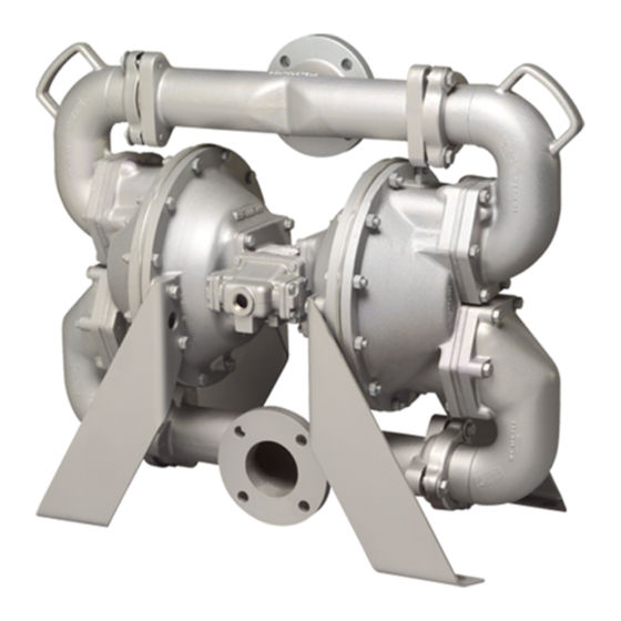
The photos shown in this manual are for general instruction only. Your specific
model may not be shown. Always refer to the parts list and exploded view drawing
for your specific model when installing, disassembling or servicing your pump.
PRINCIPLE OF PUMP OPERATION
This flap swing check valve pump is powered by compressed air and is a 1:1
pressure ratio design. It alternately pressurizes the inner side of one diaphragm
chamber, while simultaneously exhausting the other inner chamber. This causes
the diaphragms, which are connected by a common rod, to move endwise. Air
pressure is applied over the entire surface of the diaphragm, while liquid is
discharged from the opposite side. The diaphragm operates under a balanced
condition during the discharge stroke, which allows the unit to be operated at
discharge heads over 200 feet (61 meters) of water head.
Since the diaphragms are connected by a common rod, secured by plates to the
center of the diaphragms, one diaphragm performs the discharge stroke, while the
other is pulled to perform the suction stroke in the opposite chamber.
For maximum diaphragm life, keep the pump as close to the liquid being pumped
as possible. Positive suction head in excess of 10 feet of liquid (3.048 meters) may
require a back pressure regulating device. This will maximize diaphragm life.
Alternate pressuring and exhausting of the diaphragm chamber is performed by
means of an externally mounted, pilot operated, four-way spool type air distribution
valve. When the spool shifts to one end of the valve body, inlet air pressure is
applied to one diaphragm chamber and the other diaphragm chamber exhausts.
When the spool shifts to the opposite end of the valve body, the porting of chambers
is reversed. The air distribution valve spool is moved by an internal pilot valve which
alternately pressurizes one side of the air distribution valve spool, while exhausting
the other side. The pilot valve is shifted at each end of the diaphragm stroke by the
diaphragm plate coming in contact with the end of the pilot valve spool. This pushes
it into position for shifting of the air distribution valve.
The chambers are manifolded together with a suction and discharge check valve
for each chamber, maintaining flow in one direction through the pump.
INSTALLATION & START-UP
Locate the pump as close to the product being pumped as possible, keeping
suction line length and number of fittings to a minimum. Do not reduce line size.
For installations of rigid piping, short flexible sections of hose should be installed
between pump and piping. This reduces vibration and strain to the piping system. A
Warren Rupp Tranquilizer
pulsation in flow.
This pump was tested at the factory prior to shipment and is ready for operation.
It is completely self-priming from a dry start for suction lifts of 20 feet (6.096 meters)
or less. For suction lifts exceeding 20 feet of liquid, fill the chambers with liquid prior
to priming.
AIR SUPPLY
Air supply pressures cannot exceed 125 psi (8.61 bar). Connect the pump air
inlet to an air supply of sufficient capacity and pressure required for desired
performance. When the air line is solid piping, use a short length of flexible hose
(not less than 3/4" (19mm) in diameter) between pump and piping to eliminate
strain to pipes.
AIR INLET & PRIMING
For start-up, open an air valve approximately 1/2" to 3/4" turn. After the unit
primes, an air valve can be opened to increase flow as desired. If opening the valve
WARREN RUPP, INC. A Unit of IDEX Corporation • P.O. Box 1568 • Mansfield, Ohio 44901-1568 USA • (419) 524-8388 • Fax (419) 522-7867
520.012.000
8/05
SERVICE AND OPERATING MANUAL
II 2GD b T5
®
Surge Suppressor is recommended to further reduce
Models HDF3-A A A A A
Models HDF3-
Models HDF3-
Models HDF3-
Models HDF3-
HDF4-A A A A A
HDF4-
HDF4-
HDF4-
HDF4-
CE
Read these instructions completely,
before installation and start-up. It is the
responsibility of the purchaser to retain
this manual for reference. Failure to
comply with the recommendations
stated in this manual will damage the
pump, and void factory warranty.
Take action to prevent static sparking.
Fire or explosion can result, especially
when handling flammable liquids. The
pump, piping, valves, containers or
other miscellaneous equipment must
be grounded. (See page 5)
BEFORE OPERATION
Before pump operation, inspect all
gasketed fasteners for looseness
caused by gasket creep. Retorque loose
fasteners to prevent leakage. Follow
recommended torques stated in the card
attached to the new pump.
Before doing any maintenance on the
pump, be certain all pressure is
completely vented from the pump,
suction, discharge, piping, and all other
openings and connections. Be certain
the air supply is locked out or made
non-operational, so that it cannot be
started while work is being done on
the pump. Be certain that approved
eye protection and protective clothing
are worn all times in the vicinity of the
pump.
recommendations may result in
serious injury or death.
In the event of diaphragm rupture,
pumped material may enter the air end
of the pump, and be discharged into the
atmosphere. If pumping a product which
is hazardous or toxic, the air exhaust
must be piped to an appropriate area for
safe disposition.
Before maintenance or repair, shut off
the compressed air line, bleed the
pressure, and disconnect the air line
from the pump. The discharge line may
be pressurized and must be bled of its
pressure. When used for toxic or
aggressive fluids, the pump should
always be flushed clean prior to
disassembly.
Models HDF3-A & HDF4-A Page 1 Rev B
T T T T T ype 7
ype 7
ype 7
ype 7
ype 7
T T T T T ype 3
ype 3
ype 3
ype 3
ype 3
IMPORTANT
WARNING
DANGER
Failure
to
follow
these
CAUTION
CAUTION
Advertisement
Table of Contents

Related Manuals for Sandpiper HDF3-A


Summary of Contents for Sandpiper HDF3-A
- Page 1 WARREN RUPP, INC. A Unit of IDEX Corporation • P.O. Box 1568 • Mansfield, Ohio 44901-1568 USA • (419) 524-8388 • Fax (419) 522-7867 520.012.000 8/05 Models HDF3-A & HDF4-A Page 1 Rev B...
-
Page 2: Air Valve Lubrication
Halogenated Hydrocarbon solvents are AIR VALVE LUBRICATION used in pressurized fluid systems The Sandpiper pump’s pilot valve and main air valve assemblies are having Aluminum or Galvanized wetted designed to operate WITHOUT lubrication. This is the preferred mode of parts. Death, serious bodily injury and/ operation. - Page 3 1. Install the diaphragms with their natural bulge outward. Make certain that the rubber diaphragm rod bumper is installed on the rod behind each inner diaphragm Installed diaphragm. 520.012.000 8/05 Models HDF3-A & HDF4-A Page 3 Rev B...
-
Page 4: Troubleshooting
• Warren Rupp Speed Control. For manual or programmable process control. Manual adjustment or 4-20mA reception. For more detailed information on these accessories, contact your local Warren Rupp Factory-Authorized Distributor, or Warren Rupp corporate headquarters. Models HDF3-A & HDF4-A Page 4 Rev B 520-012.000 8/05... -
Page 5: Grounding The Pump
Check the local electrical code for detailed grounding instruction and the type of equipment required, or in the absence of local codes, an industry or nationally recognized code having juristiction over specific installations. 520.012.000 8/05 Models HDF3-A & HDF4-A Page 5 Rev B... - Page 6 364…E.P.D.M. Rubber Color coded: BLUE 807.016.330. Stud 365…Neoprene Rubber Color coded: GREEN 370…Butyl Rubber Color coded: BROWN 170.023.330. Capscrew, Hex Head 371…Philthane (Tuftane) List continued next page 545.007.330. Nut, Hex 807.018.110. Stud Models HDF3-A & HDF4-A Page 6 Rev B 520-012.000 8/05...
- Page 7 Valox is a registered tradename of General Electric Company. Not Shown: Warren Rupp, Rupplon, SANDPIPER, PortaPump, Tranquilizer, and SludgeMaster are registered 770.020.080. Spacer, Foot tradenames of Warren Rupp Inc. 901.006.330. Washer, Flat (used w/ foot spacer) 520.012.000 8/05 Models HDF3-A & HDF4-A Page 7 Rev B...
- Page 8 ©2005 Warren Rupp, Inc. All rights reserved. ®Warren Rupp and SANDPIPER are registered tradenames of Warren Rupp, Inc. Printed in U.S.A. Models HDF3-A & HDF4-A Page 8 Rev B 520-012.000 8/05...
-
Page 9: Declaration Of Conformity
Declaration of Conformity Warren Rupp, Inc., 800 North Main Street, Mansfield, Ohio, certifies that Air-Operated Double Diaphragm Metallic Pumps Series: HDB, HDF, S Non-Metallic, S Metallic, Containment Duty, Gas, UL, High Pressure, W, Submersible and Tranquilizers comply with the European Community Directive 98/37/EC, Safety of Machinery.
Need help?
Do you have a question about the HDF3-A and is the answer not in the manual?
Questions and answers