Advertisement
Quick Links
Advertisement

Summary of Contents for IFM Electronic VSA003
- Page 1 Installation instructions Vibration sensor VSA003 VSA004 VSA005...
- Page 2 Contents 1 Preliminary note ���������������������������������������������������������������������������������������������������3 2 Safety instructions �����������������������������������������������������������������������������������������������3 3 Functions and features ����������������������������������������������������������������������������������������3 4 Electrical connection ��������������������������������������������������������������������������������������������3 4�1 Use of a screened cable for VSAx sensors ���������������������������������������������������4 4�2 Setting instructions ����������������������������������������������������������������������������������������4 5 Installation������������������������������������������������������������������������������������������������������������4 6 Scale drawing ������������������������������������������������������������������������������������������������������5 7 Approval (Limited voltage / Current) ��������������������������������������������������������������������5 8 Maintenance, repair and disposal ������������������������������������������������������������������������5 9 Technical data ������������������������������������������������������������������������������������������������������5...
-
Page 3: Preliminary Note
1 Preliminary note • An instruction is indicated by „►“: Example: ► Mount the unit as shown� Important note Non-compliance can result in malfunction or interference� Information Supplementary note� 2 Safety instructions • Please read the operating instructions prior to set-up of the device� Ensure that the product is suitable for your application without any restrictions�... -
Page 4: Setting Instructions
► Enter the scaling for the sensor in the configuration software VES003� If the sensor is connected to channel 1: VSA003: settings → Sensors → Sensor 1 → 17500 mg VSA004 / VSA005 : settings → Sensors → Sensor 1 → 25000 mg If the sensor is connected to channel 2: VSA003: settings →... -
Page 5: Scale Drawing
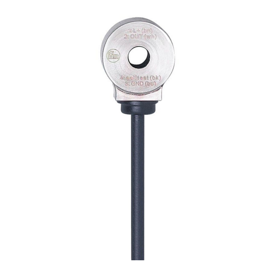
Dimensions in mm 1: shield wire H = 12 (VSA003) H = 13�5 (VSA004, VSA005) L = 1�5 m (VSA003) L = 3 m(VSA004) L = 10 m (VSA005) 7 Approval (Limited voltage / Current) The device shall be supplied from an isolating transformer having a secondary Listed fuse rated 1�0 A�...


