Table of Contents
Advertisement
Advertisement
Table of Contents

Related Manuals for IFM Electronic VNB001


Summary of Contents for IFM Electronic VNB001
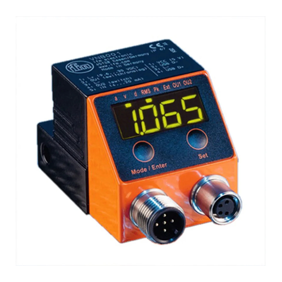
- Page 1 Operating instructions Vibration sensor VNB001...
-
Page 2: Table Of Contents
Contents 1 Preliminary note ���������������������������������������������������������������������������������������������������4 1�1 Notes on this document ���������������������������������������������������������������������������������4 1�2 Symbols used ������������������������������������������������������������������������������������������������4 2 Safety instructions �����������������������������������������������������������������������������������������������4 2�1 General ����������������������������������������������������������������������������������������������������������4 2�2 Installation and connection ����������������������������������������������������������������������������4 2�3 Tampering with the device �����������������������������������������������������������������������������5 3 Functions and features ����������������������������������������������������������������������������������������5 4 Installation������������������������������������������������������������������������������������������������������������6 5 Electrical connection ��������������������������������������������������������������������������������������������6 5�1 M8/USB interface ������������������������������������������������������������������������������������������7 5�2 History values ������������������������������������������������������������������������������������������������7... - Page 3 8�4�2 Settings �����������������������������������������������������������������������������������������������14 8�4�3 Diagram averaging �����������������������������������������������������������������������������14 9 Menu ������������������������������������������������������������������������������������������������������������������15 9�1 Explanation of the menu ������������������������������������������������������������������������������15 9�2 Parameter setting in general �����������������������������������������������������������������������17 9�2�1 Change from menu level 1 to the submenu ����������������������������������������18 9�2�2 Locking / unlocking �����������������������������������������������������������������������������18 9�3 Menu structure ���������������������������������������������������������������������������������������������19 9�3�1 Menu level 1 ���������������������������������������������������������������������������������������19 9�3�2 Submenu extended functions �������������������������������������������������������������20 9�3�3 Submenu external sensor �������������������������������������������������������������������21...
-
Page 4: Preliminary Note
Technical data, approvals, accessories and further information at www�ifm�com� 1.1 Notes on this document This document applies to devices of the type "vibration sensor" (art� no�: VNB001)� It is part of the device and contains information about the correct handling of the product�... -
Page 5: 2�3 Tampering With The Device
when installation is correctly carried out� The installation and connection must comply with the applicable national and international standards� Responsibility lies with the person installing the device� This is a class A product which is intended for use in industrial applications� The unit may cause radio interference in domestic areas�... -
Page 6: Installation
4 Installation Please note the following points when installing the unit: • Mount only in a thick housing wall (e�g� crane hook thread)� • Mount vertically to the machine surface using the spacer adapter in the direction of the strongest vibrations�... -
Page 7: 5�1 M8/Usb Interface
Pin 1: L+ 9�6���30 V DC Pin 2: Out 1 switching output or current output 4���20 mA (configurable) Pin 3: L - Pin 4: Out 2 switching output Pin 5: IN current input 4���20 mA Pin 1: VCC (5 V) Pin 2: USB D- Pin 3: L- Pin 4: USB D+... -
Page 8: Functions
6 Functions 6.1 Input function Parameter setting via the Mode/Enter and Set buttons� • External sensor for any process value (typically temperature (°C, °F)) • Scaleable input (4���20 mA) Evaluation of the measurement results as for vibration objects - Switch points early warning and main alarm adjustable - For main alarm <... -
Page 9: 6�2�3 Output Logic
6.2.3 Output logic The process values "vibration velocity" and "external sensor" are combined via a logic OR and provided at the switching output� example: 1 process value vibration velocity example: 1 example: 0 process value external sensor 1: process value vibration velocity 2: process value external sensor 3: switching output 6.3 Measuring function... -
Page 10: Operating And Display Elements
7 Operating and display elements 7.1 LED display Mode/Enter 1...8: LED display / bar graph 1: LED green a = not used 2: LED green v = vibration velocity v [mm/s] or [in/s] 3: LED green d = not used 4: LED green RMS = average value 5: LED green Pk = peak value 6: LED green Ext = process value of the external sensor... -
Page 11: 7�2 7-Segment Display
7.2 7-segment display • Displays the damage level (green, yellow, red) If the segment display changes the colour, the switch-on and switch-off delays or the hysteresis are not considered� • Displays the current vibration velocity or the current external process value 7.3 Operating mode The user must be familiar with the units used in the vibration sensor ([mm/s] or [in/s]) and in the external sensor (°C, °F, mBar)�... -
Page 12: 7�4 Operating Mode External Process Value
Colour segment display: red The external sensor has reached 95 °C� Parameters - Early warning ESP1 = 50 °C - Main alarm ESP2 = 90 °C > Outputs OU1 and OU2 are active If the segment display changes the colour, the hysteresis is not considered�... -
Page 13: Parameter Setting
8 Parameter setting Vibration velocity, external process value and self-test parameters can be set via the Mode/Enter and Set buttons� 8.1 Vibration velocity For the operating mode vibration velocity the following parameters can be set: - Measurement method (rms or peak) - Display in mm/s or in/s - Switch points - Lower limit frequency (2 Hz or 10 Hz) configurable... -
Page 14: 8�4 Averaging
Averaging 0�25; "previous diagnostic value" 17�3 mm/s; "new measurement" 14�7 mm/s (17�3 mm/s x (1 - 0�25)) + (14�7 mm/s x 0�25) = 16�65 mm/s For the VNB001 the measured time between "previous diagnostic value" and "new measurement" is 0�25 s� 8.4.2 Settings Averaging = 1: averaging deactivated Averaging = 0�01: strong averaging... -
Page 15: Menu
9 Menu 9.1 Explanation of the menu Menu level 1 EUAL Evaluation - selection of the measurement method rms "r" or peak "P" Unit - in/s or mm/s Switch point early warning If the switch point is exceeded, - OU1 switches if it is digital "no", "nc", - the yellow LED "OU1"... - Page 16 Output logic OU2 no, nc (normally open, normally closed) Submenu external sensor EHt_i EASP Scaling of the external sensor, initial value of the measuring range at 4 mA EAEP Scaling of the external sensor, final value of the measuring range at 20 mA ESP1 Switch point early warning If the switch point is exceeded,...
-
Page 17: 9�2 Parameter Setting In General
9.2 Parameter setting in general During the parameter setting process the monitoring function of the unit is maintained� It continues to monitor with the existing parameters until the parameter setting has been completed� 3 steps must be taken for each parameter setting: Select the parameter ►... -
Page 18: 9�2�1 Change From Menu Level 1 To The Submenu
9.2.1 Change from menu level 1 to the submenu ► Press [Mode/Enter] until [EF ] is ┘ displayed� Mode/Enter Set ► Press [Set] briefly� > The first parameter of the submenu is displayed (here: [LFCO])� Mode/Enter Set 9.2.2 Locking / unlocking The unit can be locked electronically to prevent unintentional settings�... -
Page 19: 9�3 Menu Structure
9.3 Menu structure 9.3.1 Menu level 1 Vibration Operating mode Ext. input... -
Page 20: 9�3�2 Submenu Extended Functions
9.3.2 Submenu extended functions... -
Page 21: 9�3�3 Submenu External Sensor
9.3.3 Submenu external sensor... -
Page 22: Maintenance, Repair And Disposal
10 Maintenance, repair and disposal ► Dispose of the device in accordance with the national environmental regulations� 11 Scale drawing 62,4... -
Page 23: Time Diagrams
12 Time diagrams 12.1 Switch-on delay for the upper limit monitor The time diagram shows the effect of the switching delay on the analogue input for an upper limit monitor (ESP1 < ESP2)� The outputs are set as normally closed (OU1 and OU2 →... -
Page 24: 12�2 Switching Delay For The Lower Limit Monitor
12.2 Switching delay for the lower limit monitor The time diagram shows the effect of the switching delay on the analogue input for a lower limit monitor (ESP1 > ESP2)� The outputs are set as normally closed (OU1 and OU2 → nc). Analogue In [°C] ESP1... -
Page 25: 12�3 Averaging For The Lower Limit Monitor
12.3 Averaging for the lower limit monitor The time diagram shows the effect of averaging for a lower limit monitor (SP1 > SP2). The outputs are set as normally closed (OU1 and OU2 → nc), AUER = 0.25 averaging [mm/s] t [s] OU 1 (n.c.) ds1, ds2, dr1, dr2 = 0 s... -
Page 26: Factory Setting
13 Factory setting Factory setting User setting EUAL mm/s 2�8 [mm/s] [mm/s or in/s] 4�5 [mm/s] [mm/s or in/s] LFCO 10 [Hz] [Hz] AUER 0,125 0 [s] 0 [s] 0 [s] 0 [s] 0 [mm/s] [mm/s or in/s] 25 [mm/s] [mm/s or in/s] EASP 0 example: [°C]...
Need help?
Do you have a question about the VNB001 and is the answer not in the manual?
Questions and answers