Table of Contents
Advertisement
Quick Links
Advertisement
Table of Contents

Subscribe to Our Youtube Channel
Related Manuals for IFM Electronic LR2759


Summary of Contents for IFM Electronic LR2759
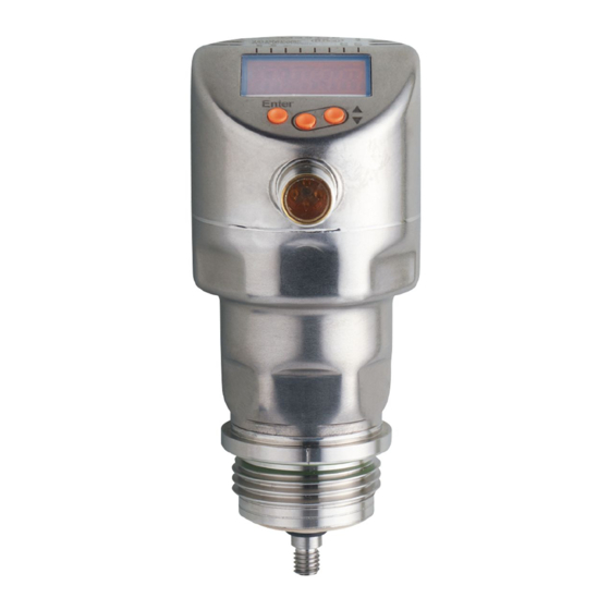
- Page 1 Operating instructions Electronic level sensor LR2759...
-
Page 2: Table Of Contents
Contents 1 Preliminary note ....................5 1.1 Symbols used ....................5 2 Safety instructions ....................5 3 Items supplied......................6 4 Getting started .....................6 5 Functions and features ..................6 5.1 Applications ....................7 5.1.1 Restriction of the application area ............7 6 Function .......................8 6.1 Measuring principle ..................8 6.2 Outputs ......................8 6.3 Other features of the unit ................9 6.3.1 Display functions ..................9... - Page 3 7.3.2 Determine probe length ..............20 7.4 Installation of the unit in the tank ..............20 7.4.1 Installation in open metal tanks ............21 7.4.2 Installation in plastic tanks ..............22 7.4.3 Note on the use according to EHEDG ..........23 7.4.4 Notes on the use according to 3-A .............23 8 Electrical connection ..................24 9 Operating and display elements ................25 10 Menu ........................26...
- Page 4 11.6.1 Re-enter probe length ...............36 11.6.2 Set to another medium ..............36 11.7 Simulation ....................36 11.7.1 Set simulation value ................36 11.7.2 Set simulation duration ..............37 11.7.3 Switch simulation on / off ..............37 12 Operation ......................37 12.1 Operation with single probe ...............37 12.2 Operation with a bypass or still pipe ............38 12.3 Function check ..................38 12.4 Operation indication ...................38...
-
Page 5: Preliminary Note
1 Preliminary note 1.1 Symbols used ► Instructions > Reaction, result […] Designation of keys, buttons or indications → Cross-reference Important note Non-compliance may result in malfunction or interference. Information Supplementary note. 2 Safety instructions • Read this document before setting up the product and keep it during the entire service life. -
Page 6: Items Supplied
• Mounting material (if necessary, a launching plate (→ 12.1), → Accessories) ► In the event of incomplete or damaged items supplied please contact ifm electronic. ► Only use accessories from ifm electronic. Accessories: www.ifm.com The optimum function is not ensured when using components from other manufacturers. -
Page 7: Applications
5.1 Applications • Food and hygienic areas. • Applications with increased requirements for protection rating and resistance (→ Technical data sheet). The unit complies with the standard EN 61000-6-4 and is a class A product. The unit may cause radio interference in domestic areas. If interference occurs, the user must take appropriate actions. -
Page 8: Function
6 Function 6.1 Measuring principle Fig. 6-1 Fig. 6-2 The unit operates on the principle of guided wave radar. It measures the level using electromagnetic pulses in the nanosecond range. The pulses are transmitted by the sensor head and guided along the probe (Fig. 6-1). -
Page 9: Other Features Of The Unit
6.3 Other features of the unit • Hygienic approvals / conformities (→ Technical data sheet) • For CIP / SIP applications (→ Technical data sheet) • Special operating mode for media with increased foam build-up (→ 11.6.2 • Tank adjustment enables suppression of undesired interference (e.g. - Page 10 Curve of the analogue signal (factory setting): I [mA] Curve of the analogue signal (measuring range scaled): I [mA] ASP2 AEP2 ① L: level [ou2] = I (factory setting) ② A: active zone = L - (I1 + I2) [ou2] = [InEG] I1: inactive zone 1 ASP2: analogue start point I2: inactive zone 2 (→...
-
Page 11: Switching Functions
6.3.3 Switching functions Via switching output OUT1 (factory setting) or additionally via OUT2 (can be set) the unit signals that a set limit level has been reached or that the level is below the limit. The following switching functions can be selected: •... -
Page 12: Damping Function
6.3.4 Damping function With unsteady level (e.g. turbulence, wave movements) display and output response can be damped. During damping the determined level values are "smoothed" by means of a mean filter; the result is a steady curve. Damping can be set by means of the parameter [dAP] (→ 11.4.10). [dAP] indicates in seconds after what time 63 % of the final value is reached in the event of a sudden jump. -
Page 13: Io-Link
6.3.7 IO-Link This unit has an IO-Link communication interface which requires an IO-Link capable module (IO-Link master) for operation. The IO-Link interface enables direct access to the process and diagnostic data and provides the possibility to set the parameters of the unit during operation. In addition, communication is possible via a point-to-point connection with a USB adapter cable. -
Page 14: Installation In Pipes
Fig. 7-1 Fig. 7-2 without adjustment Installation distances with adjustment (→ Installation distances without adjustment 7.1.7) 10 mm A1: 10 mm 20 mm A2: 50 mm 20 mm to structures in the tank (B) A3: 50 mm to structures in the tank (B) 50 mm to other sensors type LR 50 mm to other sensors type LR ø... -
Page 15: Applications With Viscous And Fast Flowing Media
7.1.3 Applications with viscous and fast flowing media For applications with viscous or flowing media and / or agitators in which the probe is exposed to lateral load: Fig. 7-3 ► Probe must not be in contact with tank wall / structures. ►... -
Page 16: Heavy Soiling
7.1.5 Heavy soiling If the medium is highly polluted, there is the risk that a bridge forms between the probe and the tank wall or structures in the tank. ► Increase minimum distances depending on the pollution intensity. 7.1.6 Heavy foam build-up and turbulence Heavy foam build-up and turbulence may lead to incorrect measurements. -
Page 17: Notes On Tank Adjustment
With increased foam build-up the setting [MEdI] = [MId] (→ 11.6.2) is recommended. 7.1.7 Notes on tank adjustment Tank adjustment (parameter [tREF]) reduces the effect of interference and ensures a higher excess gain in difficult application conditions. Carry out the tank adjustment only when the unit is installed. For the tank adjustment it is necessary to enter an "adjustment distance"... -
Page 18: Probe Installation
No tank adjustment is necessary if all installation distances (→ 7.1) are adhered to. The unit is then ready for operation without adjustment. ► In case of doubt carry out a tank adjustment (recommended!). Carry out a tank adjustment with empty tank, if possible, to detect any possible sources of interference. -
Page 19: Probe Length
7.3 Probe length 7.3.1 Shorten the probe The probe can be shortened to adapt to different tank heights. Ensure that the probe length is not below the minimum permissible probe length (Lmin) of 150 mm. The unit does not support probe lengths below 150 mm. -
Page 20: Determine Probe Length
7.3.2 Determine probe length ► Precisely measure the probe length L. The reference point is the lower edge of the process connection (figure above). ► Note the value. It is needed for setting the device parameters (→ 11.2.1). 7.4 Installation of the unit in the tank Before installing and removing the unit: Make sure that no pressure is applied to the system and that there is no medium in the tank that could leak. -
Page 21: Installation In Open Metal Tanks
7.4.1 Installation in open metal tanks ► For installation in open metal tanks, use a metal fixture to install the unit. It serves as a launching plate (R); minimum size: 150 x 150 mm for a square fixture, 150 mm diameter for a circular fixture (→... -
Page 22: Installation In Plastic Tanks
7.4.2 Installation in plastic tanks min. 150 mm. launching plate (→ 12.1) To enable sufficient transfer of the measured signal, note in case of installation in plastic tanks or metal tanks with plastic lid: ► The plastic lid must be provided with a drill hole with a minimum diameter of 150 mm. -
Page 23: Note On The Use According To Ehedg
► Insert the unit into the process connection. ► Tighten it using a spanner. Tightening torque: 35 Nm. 7.4.3 Note on the use according to EHEDG The unit has an approval according to EHEDG. It is only valid in conjunction with adapters with EHEDG approval. -
Page 24: Electrical Connection
8 Electrical connection The unit must be connected by a qualified electrician. The national and international regulations for the installation of electrical equipment must be adhered to. Voltage supply according to EN 50178, SELV, PELV. For marine applications (if approval available for the device), additional surge protection is required. -
Page 25: Operating And Display Elements
When operating voltage is applied to the unit for the first time, the probe length must be entered first (→ 11.2.1). Only then is the unit ready for operation. 9 Operating and display elements 1 to 8: Indicator LEDs LEDs Selected unit of measurement. -
Page 26: Menu
10 Menu 10.1 Menu structure Menu items highlighted in grey, e.g. [ SP2 ], are only active when assigned parameters have been selected (→ 10.2.1). main menu (→ 10.2.1) EF level (→ 10.2.2) - Page 27 Menu items highlighted in grey, e.g. [ dS2 ], are only active when assigned parameters have been selected (→ 10.2.3). III : CFG level (→ 10.2.3) ENV level(→ 10.2.4) SIM level(→ 10.2.5)
-
Page 28: Explanation Of The Menu
10.2 Explanation of the menu 10.2.1 Main menu tREF Carry out a tank adjustment. Menu item only visible if [LEnG] ≥ 260 mm. SP1 / Set point 1 / reset point at which OUT1 switches. Menu item only visible if hysteresis function is selected ([ou1] = [H..]). Upper / lower limit for the acceptable range within which OUT1 switches. -
Page 29: Level Cfg (Configuration)
10.2.3 Level CFG (configuration) Output configuration for OUT1: switching signal for level limit. Hysteresis or window function, normally closed or normally open. Output configuration for OUT2: • analogue signal for current level, 4…20 mA or 20…4 mA • switching signal for level limit. Hysteresis or window function, normally closed or normally open. -
Page 30: Parameter Setting
11 Parameter setting During parameter setting the device remains in the operating mode internally. It continues its monitoring functions with the existing parameters until the parameter setting has been completed. 11.1 Parameter setting in general 3 steps must be taken for each parameter setting: Select parameter ►... - Page 31 [C.Loc] or [S.Loc] as operation indication see (→ 12.7) • Change from menu level 1 to menu level 2: ► Press [Enter] to get to the menu. ► Press [▲] or [▼] until [EF] is displayed. ► Press [Enter]. > The first parameter of the submenu is displayed (here: [rES]).
-
Page 32: Basic Settings (Set-Up)
11.2 Basic settings (set-up) On delivery of the unit, you must first enter the probe length. The complete user menu then opens. 11.2.1 Enter probe length ► Apply operating voltage. > The initial display is shown. ► Press [Enter] and select [LEnG]. ►... -
Page 33: Configure Display (Optional)
11.3 Configure display (optional) ► Select [SELd] and set type of indication: [L] = The level is indicated in mm. [%] = The level is indicated in percent. The displayed level in % depends on the parameters: ASP2 = set value corresponds to 0 % AEP2 = set value corresponds to 100 % [OFF] = The display is switched off in the operating mode. -
Page 34: Set Switching Limits (Window Function)
11.4.3 Set switching limits (window function) ► Make sure that for [oux] the function [Fno] or [Fnc] is set. ► Select [FHx] and set the upper limit of the acceptable range. ► Select [FLx] and set the lower limit of the acceptable range. [FLx] is always lower than [FHx]. -
Page 35: Scale Analogue Signal
11.4.7 Scale analogue signal ► Select [ASP2] and set the analogue start point. ► Select [AEP2] and set the analogue end point. Setting these parameters via IO-Link is only possible if parameter [ou2] = [I] or [InEG]. More information: (→ 6.3.2) 11.4.8 Set output logic for switching outputs ►... -
Page 36: Change Basic Settings
11.6 Change basic settings Required after changes to the probe or application. 11.6.1 Re-enter probe length ► Select [LEnG]. ► Enter the probe length L. ► Press [Enter]. Note: After changing the probe length, the values for the switching limits must also be reviewed / re-entered. -
Page 37: Set Simulation Duration
11.7.2 Set simulation duration ► Select [STim]. ► Set time span for simulation. ► Press [Enter]. Setting range: 1, 2, 3, 4, 5, 10, 15, 20, 30, 45, 60 min. Factory setting: 3 min. 11.7.3 Switch simulation on / off ►... -
Page 38: Operation With A Bypass Or Still Pipe
For a correct function the unit needs a sufficiently large metal launching surface / launching plate. It is necessary for transferring the microwave pulse to the tank with optimum transmission power. For installation in closed metal tanks / metal bypass pipes, the tank lid / upper pipe section serves as a launching surface. -
Page 39: Read The Set Parameters
[S.Loc] Unit is permanently locked via IO-Link. This locking can only be removed via IO-Link. 12.5 Read the set parameters ► Briefly press [Enter] to open the menu ► [▲] or [▼] scrolls through the parameters. ► Briefly press [Enter] to indicate the corresponding parameter value for about 30 s. -
Page 40: Output Response In Different Operating States
Possible cause Recommended measures Flashing: short circuit in [SCx] + LED 7 switching output OUT1 or Remove the short circuit. [SCx] + LED 8 OUT2. [SC] + LED 7 Flashing: short circuit in both Remove the short circuit. + LED 8 switching outputs. -
Page 41: Technical Data
13 Technical data Technical data and scale drawing at www.ifm.com. Setting ranges [LEnG] Setting range 150...2000 Step increment The setting ranges for the switching limits ([SPx], [rPx], [FHx], [FLx]) depend on the probe length (L). In general the following applies: [SPx] / [FHx] L - 30 [rPx] / [FLx]... -
Page 42: Maintenance / Transport
14 Maintenance / Transport ► Keep the process connection free of deposits and foreign bodies. ► In case of heavy soiling: Clean process connection and probe. For cleaning purposes the unit can be removed from the adapter and the probe can be screwed off the unit. Before installing and removing the unit: Make sure that no pressure is applied to the system and that there is no medium in the tank that could leak. -
Page 43: Transport
Before installing and removing the unit: Make sure that no pressure is applied to the system and that there is no medium in the tank that could leak. Also always take into account the potential dangers related to extreme machine and medium temperatures. ►... -
Page 44: Factory Setting
15 Factory setting Factory setting User setting tREF nonE 50% VMR* 5 mm below SP1 ASP2 0% VMR* AEP2 100% VMR* FOU1 FOU2 SELd LEnG nonE MEdl S.LVL 50 % LEnG S.Tim S.On * VMR = final value of the measuring range = LEnG value minus 30 (in millimetres). When the LEnG value is entered, the unit calculates the basic setting. -
Page 45: Application Example
16.1 Application example ► Enter probe length (parameter [LEnG]). Example: [LEnG] = [1000] mm. ► Scale analogue output (parameters [ASP2] and [AEP2]; [AEP2] must at least be 20 % greater than [ASP2]!). Example: [AEP2] = [970] mm. ► Alternatively: Set parameter [ou2] to [H..] or [F..]. ►... -
Page 46: Unit Locking / Data Storage (As From Io-Link V1.1)
16.2 Unit locking / data storage (as from IO-Link V1.1) The IO-Link master stores all parameters of the connected sensor (except tank adjustment, see above) if configured in the master (data storage). When a sensor is replaced by a sensor of the same type, the parameters of the old sensor are automatically written to the new sensor if configured in the master and if the new sensor has the factory settings. - Page 47 More information at www.ifm.com...
Need help?
Do you have a question about the LR2759 and is the answer not in the manual?
Questions and answers