Table of Contents
Advertisement
Quick Links
Advertisement
Table of Contents

Related Manuals for IFM Electronic VKV021


Summary of Contents for IFM Electronic VKV021
- Page 1 Operating instructions Vibration sensor VKV021...
- Page 2 Contents 1 Safety instructions �����������������������������������������������������������������������������������������������3 2 Functions and features ����������������������������������������������������������������������������������������4 3 Installation �����������������������������������������������������������������������������������������������������������4 4 Electrical connection ��������������������������������������������������������������������������������������������4 5 Settings ����������������������������������������������������������������������������������������������������������������4 5�1 Measuring range ��������������������������������������������������������������������������������������������5 5�2 Switching output behaviour ���������������������������������������������������������������������������5 6 Operating and display elements ��������������������������������������������������������������������������6 7 Scale drawing ������������������������������������������������������������������������������������������������������7 8 Maintenance, repair, disposal ������������������������������������������������������������������������������7 9 Technical data ������������������������������������������������������������������������������������������������������7...
- Page 3 Preliminary note • An instruction is indicated by "►": Example: ►Check whether the unit operates correctly. Important note Non-compliance can result in malfunctions or interference� Information Supplementary note� 1 Safety instructions • Please read the product description prior to set-up of the unit� Ensure that the product is suitable for your application without any restrictions� • The unit conforms to the relevant regulations and EC directives.
- Page 4 2 Functions and features The vibration sensor detects the vibration in the system (measured / evaluated physical unit = vibration velocity)� This is converted into an analogue signal at the current output� The switching output behaviour is determined using the two setting rings�...
- Page 5 5.1 Measuring range mm/s 0���25 4���20 Response delay 1���60 5.2 Switching output behaviour t [s] 1: Time delay after the switching threshold has been exceeded 2: Time delay after the switching threshold has been exceeded 3: Switch-off 4: Switching threshold 5: Delay = vibration velocity t = time...
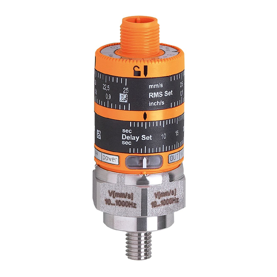
- Page 6 6 Operating and display elements RMS Set Delay Set 1: locking ring 2: setting rings (manually adjustable after unlocking) 3: LED green: voltage supply 4: M8 process connection 5: LED yellow: lights when switching threshold and time delay are exceeded 6: setting marks To achieve the setting accuracy: first position the rings to the lower end stop value, then set the requested value�...
- Page 7 7 Scale drawing M12 x1 27 M8 1: measurement axis 2: tightening torque 15 Nm 8 Maintenance, repair, disposal The operation of the unit is maintenance-free� It is not possible to repair the unit� After use dispose of the unit in an environmentally friendly way in accordance with the applicable national regulations�...
Need help?
Do you have a question about the VKV021 and is the answer not in the manual?
Questions and answers