Table of Contents
Advertisement
Quick Links
Advertisement
Table of Contents

Related Manuals for Setra Systems SRCM


Summary of Contents for Setra Systems SRCM
- Page 1 Model SRCM Operation...
-
Page 2: Table Of Contents
Contents OPERATION ..................................4 Condition Banner ..............................6 Condition Banner – Touch Screen ........................7 Operation ................................. 7 Alarms Cause Condition Banner to Turn Red ....................7 Condition Banner Functions ..........................7 Operating Condition Screen ..........................8 Pressure Value ................................. 9 Slider Bar and Set Point Values .......................... -
Page 4: Operation
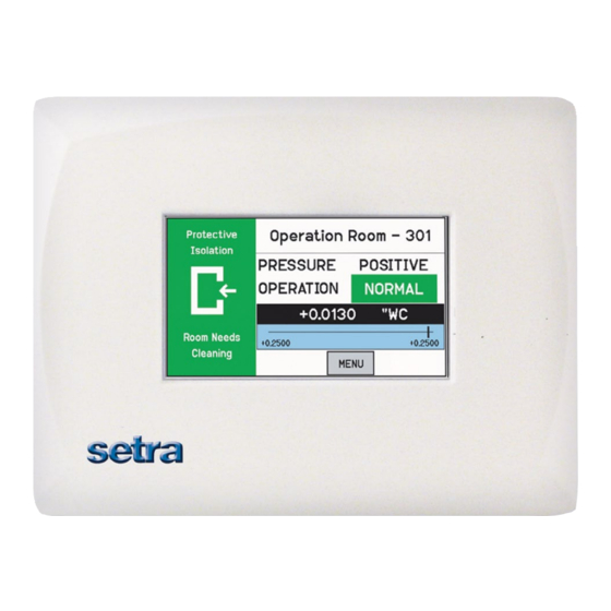
Operation The following pages describe how to operate the SRCM using the touch-screen interface. The screen has two basic functions. The primary mode of operation displays the Home screen, which shows the end-user pressure values, messages, text, and other data intended for visual pressure verification in the facility. - Page 5 ). The User switches modes by selecting slider on/slider off on the bottom of the administrative menu. The Home screen is the normal continuous operating mode of the SRCM. The Home screen shows a Condition Banner on the left one-third of the screen, and Operating Con- ditions on the right two-thirds of the screen.
-
Page 6: Condition Banner
The Condition Banner is the left 1/3rd portion of the screen that can be configured Condition Banner by the end-user or facility manager to display a message to staff on the floor. The Condition Banner can be Green, Yellow, Red Blue, depending on the message desired outside the pressurized space. -
Page 7: Condition Banner - Touch Screen
Standby, and No Action for all four colors (Red, Yellow, Green, and Blue). Functions • When Active is selected, the Occupancy Status object of the SRCM will be active. • When STANDBY is selected, then the unit shall be put into STANDBY mode (No alarms will be generated) when the corresponding color condition is selected •... -
Page 8: Operating Condition Screen
The Room Label at the top of the screen can be defined by the user to ensure the viewer understands which room is being monitored by the SRCM. See Changing Room Name page 10, to enter text for your specific room. -
Page 9: Pressure Value
A black banner displays the actual pressure reading from the space, in either inches Pressure Value of Water Column (“ WC) or Pascals (Pa). The resolution of display can vary, de- pending on desired configuration; either 2, 3, or 4 significant digits. The accuracy of measurement remains the same regardless of the number of digits chosen. -
Page 10: Active And Standby Modes
SRCM will perform all functions except that alarming will be dis- abled (both audible and visual alarms). The STANDBY mode is designed to put the SRCM into a mode where room pressurization is not critical, such as cleaning, patient transfer, or longer-term unoccupied status. Note that this op- eration can be password protected so that only an Operator or a Supervisor can make this change. -
Page 11: Menu Screens
Save Settings and Exit * Calibration is only required for highly accurate measurement needs such as those needed to comply with federally mandated regulations. See the SRCM Product Data Sheet for more information. Upon initial installation, the Setup Unit screen should be used to define installation... -
Page 12: Setup Unit
The SRCM can take as input, the signal from two separate pressure transducers as well Setup Unit as temperature, humidity, and user defined (ex. CO ) inputs for up to two rooms. These are configured for either Primary Room or Secondary Room (an anteroom is an example of a secondary room). -
Page 13: Room Parameters
The SRCM can display up to four (4) parameters for each of 2 rooms. The pa- Room Parameters rameters can be Pressure, Temperature, Humidity, and the fourth user defined (Ex., CO ). Start with the Primary Room and set up the Parameters to be moni- tored and displayed on the default or home screen. -
Page 14: Analog Inputs
This takes an analog input from any transducer or transmitter: pressure, temperature or humidity. If an external transducer is used, the full scale values and parameters need to be configured into the SRCM so the unit understands the scale of measure- ment being received on inputs ADC CH-1 or ADC CH-2. -
Page 15: Changing Room Name
The following is an example using a humidity sensor to measure primary room relative humidity. The range is 0-98 %RH with a 0-10 VDC output. The room name shown on the top part of the Home screen is changed using the Changing Room Name Room Label button. -
Page 16: Setup Display
The Setup Display screen permits authorized users (based on password level) to Setup Display configure Condition Banner messages and other Home screen options. There are four tabs for display customization; General, Advanced, Condition Banner, Set Time and Date. The General tab allows the user to define messages for each Condition Banner General Tab —... -
Page 17: Advanced Tab
1-4. After modifying this parameter, press Save & Exit to view the brightness and contrast on the Home screen display. Depending on the lighting and viewing conditions in the final space, different contrast levels can improve readability of the SRCM. Contrast level of Home screen. Adjust from 1-4 for... -
Page 18: Pressure Resolution
This could be a Nurse or a Lab Technician. The SRCM was designed to make interaction with the unit as easy as possible for the Operator. Chang- es to messages and to the room mode requires simply touching active areas of the display. -
Page 19: Condition Banner Tab-Customizing Blinking Screens
The Condition Banner can be used for control function as well as pure communi- Condition Banner Tab- cation. There are three choices for each color: Active, Standby, and No Action. Customizing Blinking Screens These apply to the right Used for setting side of the Home Screen actions that is associated with... -
Page 20: Full Screen Condition
Full Screen Condition Customers may want a minimal user interface and want to switch be- tween Active and Standby Modes and clearly convey the status of the Banner and Active Standby room. Mode Application Note: Any color can be associated with any action: Active, Standby, or No Action. - Page 21 5. With this setup the unit is in Active Mode. The Full Screen Display will look like the following with the text that was specified in step 2: 6. If the User changes to Standby by touching the section to the right of the PRESSURE, then the display will show up in yellow with the text that was specified in step 3.
-
Page 22: Set Time & Date Screen
The Set Time & Date tab is used for setting the time and date of the SRCM. This time Set Time & and date is used to time stamp the event log. See Event Log Section. Date Screen Note: If power is lost to the unit, the time, and date need to be reset. If BACnet is used and is connected to the network, the time and date will automatically be retrieved. - Page 23 Audible Alarm Enables or disables the audible buzzer. Regardless of whether audible alarming is enabled or disabled, the red ALARM condition will show on the Home screen, annunciate to an SRAN, and propagate to a configured Digital Output. If an alarm occurs and the audible alarm is enabled, a new SILENCE button will appear on the Home screen so that the operator can silence the audible alarm.
-
Page 24: Alarms Disabled When Door Open & Buzzer For Door
The SRCM is able to configure the Room status to disable the Alarms when Alarms Disabled when Door Door is open. This function is used when there will be high traffic through Open & Buzzer for Door the area and the user wants to disable any alarms that are occurring as the Warning result of the door being open. -
Page 25: Alarm Set Point
When the room is then set to Positive, Neutral, or Negative, the setpoints and con- ditions configured here are in effect for alarm and warning conditions. The SRCM has a great deal of flexibility to define alarm conditions. Alarms and warnings Alarm Matrix can be configured for primary and secondary rooms, and for the door. - Page 26 Toggle High Priority Display Background Remarks Text (Maxi- Primary Secondary mum eight Pressure Pressure characters) Disabled Alarm Shows Alarm for second- ary room if secondary room is selected for display. If the pressure to display is selected as Primary, display switches to the secondary room to show the alarm.
-
Page 27: Calibration And Self Test
Calibration and This page is used for calibration of the internal pressure transducer sensor and testing operation of hardware circuitry. Calibration is only required for Self-Test highly accurate measurement needs such as those needed to comply with federally mandated regulations. Calibration should only be performed by qualified personnel. -
Page 28: System Information
Zero Adjust Pressing Zero Adjust button will bring up a “Is zero pressure applied?” message. If yes, press OK. If the zero measure- ment is within 10% of the factory zero measurement stored in the unit, the zero value will be reset. Note: Zero Adjust should only be performed after the unit has been operating for 30 minutes in the installed location. -
Page 29: Usb Configuration Cloning
Exit function is used to properly save your configuration. This “master” setup will then be downloaded to the thumb drive and for use uploading to other units. As soon as the thumb drive is connected to the SRCM it will be recognized and bring up a Drive Connected menu. - Page 30 Review the various Menu screens of the slave unit and sub- sequent units to confirm the proper configuration is stored. In most cases the only change that will be required to clone SRCM units is Primary and Secondary Room labels that match the location of installation.
-
Page 31: Updating Firmware
Note: Before updating firmware, perform USB Configuration Cloning. Refer to USB Configuration Cloning on previous page. The USB port can be used for upgrading the SRCM firmware in the field. To upgrade the firmware you must first download the firmware for the lat- est versions of the hex file for the host controller, the USB hex file and the BACnet hex file, these are EMS1009.hex, usb.hex and BACnet.hex. -
Page 32: Network Setup
The BACnet setup screen is enabled by pushing position 1 switch (labeled Network Setup MAC) to the on (right) position. After configuration the switch must be moved to the off (left) position. Five position dip switch location The Network Setup screen gives the option for the user to configure the Network and other parameters which have to be read from the network. - Page 33 4. APDU Timeout - Indicates the amount of time in milliseconds between retrans- missions of the APDU requiring acknowledgement for which no acknowledge- ment has been received. The default value for this property will be 3,000 ms and max can be 65535. Save and Exit to save settings or cancel to cancel setting changes.
-
Page 34: Event Log
Event Log The SRCM can be enabled with an audit trail of changes made to the configurations/ modes of the system by Supervisor and Operator. When the Supervisor / Operator changes any configuration through the menu, the action is captured and stored in a string covering the User profile Screen name where the parameter is changed. -
Page 35: French Language Support On Default Screen & Data Entry Screen
The home screen can be setup to show French Language words French Language using the Setup Display Menu Support on Default Screen & Data Entry Screen The following screens show the difference between English and French Home screens. Default screen for English version. -
Page 36: Data Entry Screen For French Version
On the default screen the following changes will be made for the French version. PRESSURE PRESSION OPERATION OPĖRATION NEGATIVE NĖGATIVE NEUTRAL NEUTRE STANDBY ATTENTE DOOR PORTE WARNING ALERTE ALARM ALARME TEMPERATURE TĖMPERATURE SILENCE, NORMAL, HUMIDITY, RESET do not change When the language is selected as French in the setup display screen, French characters entry in the data screen will be enabled. - Page 37 French Version—Letter A French Version—Letter E...
- Page 38 French Version—Letter U French Version—Letter Y...
- Page 39 French Version—Letter I French Version—Letter O...
- Page 40 French Version—Letter C French Version—Letter N...
-
Page 41: Troubleshooting
The MS/TP cable runs are broken. Locate the break and correct the wir- ing. MS/TP connections at the module Respect polarity of the wires on a were reversed. MS/TP network. The SRCM does not have power. Apply power to the SRCM. -
Page 42: Returning Products For Repair
RETURNING PRODUCTS FOR REPAIR When returning a product to Setra Systems, the material should be carefully packaged and shipped prepaid to: Setra Systems, Inc. 159 Swanson Road Boxborough, MA 01719-1304 Attn: Repair Department To assure prompt handling, please refer to return instructions on our Web site at http://www.setra.com/tra/re- pairs/cal_rep.htm.
Need help?
Do you have a question about the SRCM and is the answer not in the manual?
Questions and answers