
Related Manuals for Setra Systems DATUM 2000


Summary of Contents for Setra Systems DATUM 2000
- Page 1 DATUM 2000™ Operating Instructions Setra Systems, Inc. 159 Swanson Road, Boxborough, MA 01719 800.257.3872 • www.setra.com...
-
Page 2: Table Of Contents
7.0 Installation of pressure fittings for the manometer ........... 13 8.0 Calibrating the Datum 2000™ ..................14 8.1 Calibrating the Datum 2000™using known pressures .......... 14 8.2 Calibrating the Datum 2000™using an external reference voltage ....... 15 Calibrating the DATUM 2000™ for a transducer using the internal reference voltage ..................... -
Page 3: Introduction
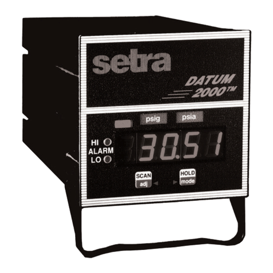
Thank you for purchasing a Setra DATUM 2000™ meter or manometer. Setra’s DATUM 2000™ is a compact dual channel meter with a 4 1/2 digit LED display designed to mate with one or two transducers or transmitters with a connection. -
Page 4: Connecting A Transducer To The Datum 2000
The DATUM 2000™ has two groups of input terminals, one for each channel. Figure B (page 6) shows the terminal block connector on the back of the DATUM 2000™ and describes each position of the connector. Figure A shows a typical setup of a DATUM 2000™... -
Page 5: Transducers (4 Wire Or 4 Terminal Devices)
2.3 Transmitters (4 wire or 4 terminal devices) Connect the + excitation to pin 5 (CH2: pin 11) to supply 24 volts to the transducer. If your transducer requires 12 volt excitation, connect the + excitation to pin 10 (CH2: pin 10). Connect the - excitation to ground, pin 9 (CH2: pin15). - Page 6 Figure B Terminal block connector Setra transducer* Setra transmitter* Description w/ red cable w/ gray cable w/ gray cable Ground Hi ALArm Lo ALArm Ch. 1/ Ch. 2 +24 volts excitation White Ch. 1 +In Yellow Green Ch. 1 -In Brown White Ch.
-
Page 7: Operating Notes
“UndEr”. 3.2 Sampling rate The DATUM 2000™ will read the channel, 2 to 3 times a second. The speed of the update is determined by the voltage of the channel being read. If the meter has two channels calibrated, it will display each channel for 8 readings, and then switch to the other channel. -
Page 8: User Setups
4.0 User setups The menu tree below represents the meter program structure. To enter the menu and select a channel, press and hold the SCAN/adj and HOLD/mode keys for 8 seconds, then release; the display will alternate between "cal" and "noYes" for ten seconds.* To specify "yes"... -
Page 9: Set "Offset
5.0 Set "offset" (please read before attempting procedure) Note: The channel must be calibrated before the offset is adjusted. The "OFFSET" command allows you to adjust the reading relative to a known value. To set the "OFFSET" use the following procedure: Step 1. - Page 10 Step 5. Press the HOLD/mode key to display the number "0". Note: The decimal point that was set during calibration (CAL_U, CAL_C) will be displayed. Step 6. Set the value you wish the meter to display at the presently applied pressure. Press the SCAN/adj key to move the numbers up (+).
-
Page 11: Hi/Lo Alarm Setpoints
6.0 HI/LO alarm setpoints (please read before attempting procedure) Note: The channel must be calibrated before the alarm points are set. The "ALAr" command allows you to set high and low pressure alarm points. The HI alarm or LO alarm indicator light is lit if the applied pressure exceeds the set values. The alarm output signals are available at the terminal strip. -
Page 12: Alarm Output
Step 6. Repeat the same procedure as in Step 5 to set the HI alarm point. After the number is accepted the DATUM 2000™ will resume normal operation. 6.1 Alarm output The alarm outputs are available on the terminal strip on the back of the meter. The alarm signals available are: HI ALARM (pin 2), LOW ALARM (pin 3), and CH1/CH2 (pin 4). -
Page 13: Installation Of Pressure Fittings For The Manometer
7.0 Installation of pressure fittings for the manometer Your transducer is designed for most accurate operation when subjected to pressures within the designated pressure range. Refer to catalog bulletin specifications for proof pressure limits. Subjection to excessive pressure voids the warranty. -
Page 14: Calibrating The Datum 2000
Note: If on power up, the DATUM 2000™ display alternates between "cal" and "no Yes", it has not been called calibrated at the factory. If the DATUM 2000™ (Channel 1 or 2) displays numbers on power up, one or both channels have been calibrated at the factory. -
Page 15: Calibrating The Datum 2000™Using An External Reference Voltage
8.3 Calibrating the DATUM 2000™ for a transducer using the internal reference voltage The DATUM 2000™ has a very stable internal reference voltage which can be used for calibration if the above methods cannot be used. For the first pressure point the +IN, -IN and ground should all be shorted together, pin 6, pin 7,and pin 9 (CH2: pin 12, pin 13, and pin 15). -
Page 16: Calibrating The Datum 2000™ For A Transmitter Using The Internal Reference Voltage
8.4 Calibrating the DATUM 2000™ for a transmitter using the internal reference voltage The DATUM 2000™ has a very stable internal reference voltage which can be used for calibration with transmitters. Before proceeding you must locate the label on the bottom of the DATUM 2000™... - Page 17 Enter the pressure that corresponds to this input current according to the formula above; the value of the reference voltage and the "mA" input impedance is recorded on the serial label on the bottom of the DATUM 2000™. 1st Example: A 1000 PSI transmitter outputs 4 mA at 0 PSI and 20 mA at 1000 psi.
-
Page 18: Calibrating Voltage Input And Current Input
9.0 Calibrating voltage input and current input (Please read before attempting procedure) CAL_U and CAL_C commands allows you to calibrate the DATUM 2000™ by entering two data points. (Calculate the pressure for the 2 calibration points before beginning this procedure.) The DATUM 2000™ will determine the conversion factor and display the applied pressure in the desired engineering units. - Page 19 Step 4. Press the SCAN/adj key to display "OFFSET". Step 5. To calibrate voltage in (transducer), press the SCAN/adj key to display "CAL U". (If calibrating for voltage input, proceed to Step 7, if not, proceed to Step 6 to calibrate for current input.) Step 6.
- Page 20 Note: The pressure or voltage/current must be applied to the appropriate channel before entering this data point. Caution: Do not try to calibrate Channel One of the DATUM 2000™ manometer with a voltage input, this will damage the unit and void the warranty. Never apply a voltage signal to the Channel One inputs (see page 14).
-
Page 21: Erasing Calibration In A Channel
In Steps 8 and 9, enter a value of 0. (It does not matter what, if any, voltage or current signals are applied to the DATUM 2000™ when you use the calibration procedure to erase a channel, as long as they do not exceed the DATUM's input specifications.) - Page 22 (This page is intentionally left blank)
-
Page 23: Datum 2000™ Manometer Specifications
11.0 DATUM 2000™ manometer specifications w/Models 204/204D w/Model 239 w/Model 270 Type of pressure Gage Differential Gage measurement Absolute Gage Absolute Vacuum Barometric Differential Standard ranges 0 to 25, 50, 100, 250, 0 to 0.5, 1.0, 2.5, 5, 0 to 5, 10, 20, 50,... -
Page 24: Datum 2000™ Meter And Manometer Specifications
Accuracy (readout only) At 73°F (23°C) ±0.01%R ± 1 digit At 60°F to 95°F (16° to 35°C) ±0.04%R ± 1 digit Analog output Transducers Same as transducer output voltage No analog output; the DATUM 2000™ terminates the Transmitters current loop... -
Page 25: Panel Mount Instructions
12.0 Specifications continued Adjustment capabilities (accessible through the user set-up menus) Voltage inputs +11 to -11 volts Current inputs 0 to 20 mA Maximum reading +31999 Minimum reading -9999 Input specifications Transmitter input signal 4-20 mA Transmitter input impedance 150 ohm Transmitter input voltage drop 3 VDC (max.) Transducer input signal... - Page 26 . Slide the screw down until it contacts the panel. Now tighten the screw against the panel. Note: You can press against the top of the screw with your thumb to maintain the proper orientation as shown. Note: You may need to bend the panel mount tabs to their new position after they are used.
-
Page 27: Fcc Waring
14.0 "FCC warning" WARNING: Changes or modifications to this unit not expressly approved by the party responsible for compliance could void the user's authority to operate the equipment. NOTE: This equipment has been tested and found to comply with the limits for a Class A digital device, pursuant to Part 15 of the FCC Rules. -
Page 28: Return Instructions
Many times only minor field adjustments may be necessary. When returning a product to Setra, the material should be carefully packaged and shipped prepaid to: Setra Systems, Inc. 159 Swanson Road Boxborough, MA 01719-1304...
Need help?
Do you have a question about the DATUM 2000 and is the answer not in the manual?
Questions and answers