Table of Contents
Advertisement
Advertisement
Table of Contents

Related Manuals for Setra Systems 370


Summary of Contents for Setra Systems 370
- Page 1 Operator's Manual Model 370 Digital Pressure Gauge...
-
Page 3: Table Of Contents
Table of Contents INTRODUCTION About this Manual ..................iii SECTION ONE Installing the Model 370 ................1 SECTION TWO: SUMMARY OF FUNCTIONS 2.1 Keyboard Functions ................3 2.2 Display Symbol ..................4 2.3 Display Messages ................5 SECTION THREE: DIGITAL PRESSUREGAUGE FUNCTIONS 3.1 Entering a Number or Function ............ - Page 4 II.1 Zero Calibration ................. 27 II.2 Span Calibration ................28 Appendix III: RS-232 SERIAL DATA COMMUNICATIONS III.1 Interfacing Setra 370 to a Computer ..........29 III.2 Sending Commands to the 370 ............30 III.3 Receiving Data from the 370 ............. 31 III.4 Immediate and Repetitive Print Modes ..........
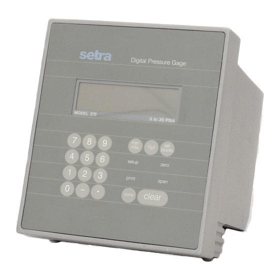
- Page 5 Introduction Congratulations, and thank you for purchasing a SETRA Model 370 high accu- racy Digital PressureGauge. Its ease of operation and durable construction will provide years of reliable service. While thegauge is easy to operate, it is advis- able to read this guide carefully before use. It is designed to help you take full advantage of the functions and performance of the gauge.
- Page 6 OUTLINE DRAWING Side View 8.55 Rear View AC Power 8.55 Pressure Port RS-232 I/O On/Off (Battery Only)
-
Page 7: Section One
0.02% FS system accuracy. The unusual ergonomic design of the Model 370 allows it to be used as a bench top instrument (with keypad and display at the proper angle for viewing), as a portable device with a built in carry handle, or as a rack mount instrument with the optional 19"... - Page 8 Portability and Accuracy Right Where You Need It Display min/max 6 digit LCD with Annunciators for Tracks Minimum and Maximum Alarms, Min/Max values and Values Encountered. Engineering Units. f(p) Programmable Non- Linear Function Key for Barometric Ranges. Digital Pressure Gage Converts True Baromet- ric Pressure To Sea Level Pressure.
-
Page 9: Section Two: Summary Of Functions
Section Two SUMMARY OF FUNCTIONS 2.1 KEYBOARD FUNCTIONS print Send information to a printer or other peripheral. conv Convert engineering units being displayed. Display HI and Lo Alarm setpoints. points zero Enter relative or absolute tare value. Display minimum and maximum value encountered. Clear the number or key sequence being entered or displayed. -
Page 10: Display Symbol
2.2 DISPLAY SYMBOLS The readings are within the user defined stability requirement. The reading shown is given in hectopascals. The reading shown is given in pounds per square inch. The reading shown is given in inches of mercury. inHg The reading shown is given in millibars. mbar The reading shown is given in millimeters of mercury. -
Page 11: Display Messages
The pressure applied exceeds the rated range of the sensor. DISPLAY The gauge is acquiring a stable reading. BUSY Other messages which are displayed in the course of using the various functions of the Model 370 are explained in the sections of the manual concerning those functions. -
Page 13: Entering A Number Or Function
This automatically returns the gauge to display mode, without affecting any other functions which may be in use. To reset the Model 370 to its power up condition, press "-", then CLEAR. This clears the zero/tare value, shuts off MIN/MAX, and converts back to the original engineering units. -
Page 14: Converting Engineering Units
Section 5 for displaying altitude. 3.5 TRACKING MIN AND MAX VALUES To use the Model 370 to track the minimum and maximum pressures applied to the sensor, enter the tracking mode by pressing SETUP, then MIN/MAX. To examine the values stored, press MIN/MAX. The gauge will display "HI"... -
Page 15: Setting And Checking Alarm Setpoints
3.6 SETTING AND USING ALARM SETPOINTS The Model 370 has an alarm capability which will indicate when the pressure applied has exceeded a high or a low setpoint. The annunciators are an audible tone, a display message of "HI ALARM", and a message sent through the communications port. -
Page 16: Tares And Offsets
3.7 USING THE TARE AND ZERO FUNCTION The TARE function on the Model 370 gives you a way of setting the displayed reading to zero or of subtracting a specified offset so that you can monitor changes in pressure relative to a known starting point. This is done by creating a tare value which will be subtracted before each up- dated reading is displayed. -
Page 17: Printing Out Information
3. Make sure the printers on-line light is on. 4. Press PRINT to send the reading in the Model 370 display to the printer. NOTE: When using a printer set the baud rate of the gauge to match that of the printer (see Appendix I). -
Page 18: Repetitive Printing
3.9 REPETITIVE PRINTING It is sometimes desirable to record pressure measurements at fixed intervals of time. To print at fixed intervals, follow this procedure: 1. Connect a printer as outlined in Section 3.8. 2. Enter the number of seconds between readings. 3. -
Page 19: Printing Setup Status
3.10 PRINTING SYSTEM STATUS To get a summary of the condition of all active functions, press SETUP, then press PRINT. A sequence of information will be printed indicating the range of the gauge and the status of any functions which are currently in use, as shown in this example. -
Page 21: Section Four: Advanced Pressuregauge Functions
Section Four ADVANCED PRESSURE GAUGE FUNCTIONS USER DEFINED ENGINEERING UNITS The Setra Digital Pressure Gauge has several built-in engineering units conversions which are accessed simply by pressing CONV. If you want to display pressure in units other than those provided, use the following procedure. - Page 22 Transmit: 70307Ug/cm2 the 370 will now report in g/cm2 to an interrogation. The conversion ratio will be saved and used for the user definable engineering units until a new ratio is entered, even if the power is shut off and turned back on.
-
Page 23: Digital Altimeter Setting Indicator (Dasi)
DIGITAL ALTIMETER SETTING INDICATOR The Model 370 may be used to display corrected sea-level pressure by "reducing" true barometric pressure at a known elevation to what the pressure would be at sea-level at the same latitude and longitude. This function is only available on gauges with barometric or absolute pressure sensors. -
Page 25: Section Five: Displaying Altitude
Section Five DISPLAYING ALTITUDE The Model 370 Digital Pressure Gauge can be used to display a variety of altitude measurements. It may be used as an altimeter calibrator, a standard altimeter, a true corrected altimeter (self corrected or remote), or as a relative altimeter. -
Page 26: True Corrected Altitude
DISPLAYING TRUE ALTITUDE The Model 370 can function as an altimeter displaying true altitude by correcting the above Standard Atmosphere conversion for the local barometric pressure. This correction can be setup two ways. If you are starting at a known station elevation, use the following procedure: 1. - Page 27 If you are not at a known elevation, the gauge may be used in true altimeter mode by obtaining an Altimeter Setting Indication (sea level corrected pressure) from a local airport or weather station, and following this procedure: 1. Press the CONV key until the engineering units of the known sea level pressure appears in the display.
-
Page 28: Relative Altitude
MEASURING RELATIVE ALTITUDE To measure relative altitude in either Standard or True Altimeter Mode, a reference altitude may be established by setting the displayed reading to zero, or by offsetting it by a specified amount entered as a tare value. 1. -
Page 29: Appendix I: Setup Functions
Appendix I SETUP FUNCTIONS FORMATTING BAUD RATE The Setra Digital Pressure Gauge is capable of interfacing with a wide variety of computers or other devices through the RS-232 serial communications port. Devices which are connected this way must be set up to communicate at the same rate of speed. -
Page 30: Disabling Beeper
"OK" is displayed whenever the pressure is changing by less than the Stability Indicator Limit from the last display update to the next. The Stability Indicator Limit may be used when the Model 370 is serving as a Secondary Pressure Standard, to ensure that calibration pressures being applied to another device are accurate and stable within a given amount. -
Page 31: Omitting Engineering Units
OMITTING ENGINEERING UNITS Some applications may require frequent switching from one engineering unit to another. The Model 370 can be setup to omit one or more of the built-in engineering units to reduce the number of times CONV must be pressed to get from one unit of measure to the next. -
Page 32: Self Diagnostics
SELF DIAGNOSTICS The Model 370 has a built-in self diagnostic procedure. This procedure prompts an operator to verify that the gauge is fully operational, (but does not verify proper calibration), by checking the keyboard, the keyboard decoder, the display, and a checksum test on internal memory. -
Page 33: Appendix Ii: Calibration
Appendix II CALIBRATION The zero and span of the Model 370 Digital Pressure Gauge may be calibrated using the following procedures. A high accuracy primary pressure standard is recommended as the calibration source, since the high accuracy of the Model 370 will be adversely affected if the calibration pressure is not of equal or greater accuracy. -
Page 34: Ii.2 Span Calibration
SPAN CALIBRATION To perform the span calibration on the Model 370, it is necessary to apply both the zero and the full scale pressures, as in the following procedure: 1. Make certain the gauge is in a stable temperature environment for several hours before calibration. -
Page 35: Appendix Iii: Rs-232 Serial Data Communications
Appendix III RS-232 SERIAL DATA COMMUNICATIONS The Setra Model 370 Digital Pressure Gauge is equipped with a bidirectional RS-232 interface which allows communications between the gauge and other devices which are also equipped with an RS-232 interface. This section provides detailed technical information showing how to operate the Model 370 remotely from a computer. -
Page 36: Iii.2 Sending Commands To The 370
III.2 SENDING COMMANDS TO THE GAUGE All the functions of the Model 370 may be executed by sending the appropriate command from the computer to the gauge. The commands are standard alphabetic characters which correspond to keys on the front keypad of the gauge. -
Page 37: Iii.3 Receiving Data From The 370
III.3 RECEIVING DATA FROM THE GAUGE There are several types of messages which the gauge may send in response to the various commands. The immediate response to the PRINT command interrogation is the most common message. It is a string of characters consisting of the reading on the display and other information. -
Page 38: Iii.4 Immediate And Repetitive Print Modes
III.4 IMMEDIATE AND REPETITIVE PRINT MODES Two print modes are available on the Model 370, as discussed in Sections 3.8 and 3.9. The immediate print interrogation, used in the example above, is the preferred method of getting pressure data to a computer program. -
Page 39: Iii.7 Rs-232 Interface Hardware
"null modem" cable is required. This is simply a cable which connects pin 2 and 3 of the Model 370 to pin 3 and 2 of the other device respectively by crossing them in the cable. This kind of cable is also available from SETRA, or from any computer hardware vendor. -
Page 41: Appendix Iv: Accessories And Options
ACCESSORIES AND OPTIONS IV.1 BATTERY / RECHARGER OPTION The Model 370 Digital Pressure Gauge can be operated as a portable instrument with the battery/recharger option. The battery option is designed to allow a standard 8 hour workshift, followed by a 16 hour recharge cycle. -
Page 42: Iv.2 In Case Of Difficulty
IV.2 IN CASE OF DIFFICULTY If a problem persists which cannot be solved by reading the appropriate sections of this manual, contact a SETRA Applications Engineer for assistance at the toll free number: 1-800-257-3872 IV.3 OPTIONS 1. Internal rechargeable battery pack. 2. -
Page 43: Iv.4 Specifications
Model 370 Specifications Pressure Ranges Type of Pressure Pressure Range Display Altitude Range Barometric 600 to 1100 mbar 600.00 to 1100.00 -1000 to 13,800 ft. 800 to 1100 mbar 800.00 to 1100.00 -1000 to 6,400 ft. Absolute 0 to 10 psia 10.0000... -
Page 45: Appendix V: Warranty Information
Appendix V WARRANTY INFORMATION V.1 LIMITED WARRANTY - PRESSURE PRODUCTS SETRA warrants its products to the original consumer purchaser against defects in materials and workmanship for a period of one year from the date of sale by SETRA, as shown in its shipping documents, subject to the following terms and conditions: Without charge, SETRA will repair or replace products found to be defective in materials or workmanship within the warranty period provided that:... - Page 48 Published by: Setra Systems, Inc. 159 Swanson Road, Boxborough, MA 01719 Telephone (800) 257-3872 or (978) 263-1400 Telefax (978) 264-0292 Web: www.setra.com All Rights Reserved SS0470 REV D 06/06...
Need help?
Do you have a question about the 370 and is the answer not in the manual?
Questions and answers