Table of Contents
Advertisement
Quick Links
Advertisement
Table of Contents

Related Manuals for Setra Systems SRCM


Summary of Contents for Setra Systems SRCM
- Page 1 Model SRCM Operation...
-
Page 2: Table Of Contents
Table of Contents Operation …………………………………………………………………………………………1 Home Screen ……………………………………………………………………………………2 Condition banner …………………………………………………………………………………2 Condition Banner— Touch-Screen Operation ………………………………………3 Operating Condition Screen …………………………………………………………4 Pressure Value ………………………………………………………………………5 Slider Bar and Setpoint Values ………………………………………………………5 Slider Bar On/Off ……………………………………………………………………6 Occupied and Standby Modes …………………………………………………………6 Menu Screens …………………………………………………………………………7 Setup Unit ………………………………………………………………………………………8 Primary Room …………………………………………………………………………8 Secondary Room... -
Page 4: Operation
The second mode of operation is the Ad- ministrative Menu (Menu) screen, which permits setup, configuration, and changes to how the SRCM operates. After changes have been performed on the Menu screen, func- tions are saved and operation returns to the Home screen. -
Page 5: Home Screen
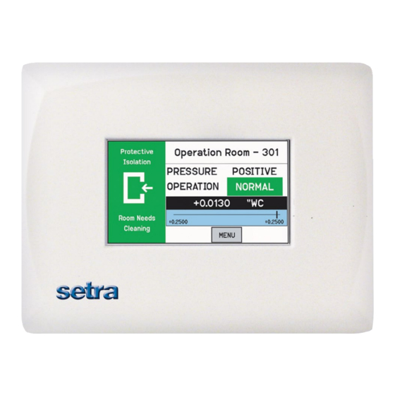
Home Screen The Home screen is the normal continuous operating mode of the SRCM. The Home screen shows a Condition Banner on the left one-third of the screen, and Operating Con- ditions on the right two-thirds of the screen. Room Label... -
Page 6: Condition Banner- Touch-Screen Operation
See Section: Setup Display, page 11, for instructions on how to setup the Condition Banner. When the Operating mode of the SRCM is set for PRESSURE = STANDBY, the top part of all three banners will display STANDBY to indicate that active use of the SRCM has been suspended and no alarms will occur. -
Page 7: Operating Condition Screen
The Room Label at the top of the screen can be defined by the user to ensure the viewer understands which room is actively being monitored by the SRCM. See Sec- tion, Setup Display, page 10, to enter text for your specific room. -
Page 8: Pressure Value
A black banner displays the actual pressure reading from the space, in either Water Column inches (“ WC) or Pascals (Pa). The resolution of display can Pressure Value vary, depending on desired configuration; either 2, 3, or 4 significant digits. The accuracy of measurement remains the same regardless of the number of digits displayed. -
Page 9: Slider Bar On/Off
first enter a password to proceed with the change. In OCCUPIED mode, the full function of the SRCM is active. In STANDBY mode, the SRCM will perform all functions except that alarming will be disabled (both audible and visual alarms). -
Page 10: Menu Screens
Menu (Menu). If passwords are enabled, the user is required to enter the correct password before being authorized to make changes. From the Administrative Menu, the user can set all operating parameters of the SRCM. This includes initial setup, commissioning, calibration, customizing the displays, and warning and alarm parameters. -
Page 11: Setup Unit
When two transducers are used, the Home screen display of the SRCM can toggle between each space to indicate the status of each room momen- tarily, cycling from one to the other a few seconds apart. -
Page 12: Primary Analog Output
Room. If an external transducer is used, the full-scale values and other parameters need to be configured into the SRCM so the unit understands the scale of measure- If selecting Analog Ch1 or Analog Ch2 for either Primary of Secondary... -
Page 13: Changing Room Name
Changing Room Name ment being received on the inputs Analog Ch1 or Analog Ch2. The room name shown on the top part of the Home screen is changed using the Room Label button. The Room Name entry box appears in the middle of the Setup Unit display. -
Page 14: Setup Display
Setup Display The Setup Display screen permits authorized users (based on password level) to configure Condition Banner messages and other Home screen options. There are three tabs for display customization; General, Advanced, and Condition Banner. General Tab– The General tab allows the user to define messages for each Condition Banner Customizing the color. -
Page 15: Advanced Tab- Customizing The Operating Condition Screen
1-4. After modifying this parameter, press Save & Exit to view the brightness and contrast on the Home screen display. Depending on the lighting and viewing conditions in the final space, different con- trast levels can improve readability of the SRCM. Contrast level of Home screen. Adjust from 1-4... -
Page 16: Supervisor And Operator Passwords
This can be a Nurse or a Lab Technician. The SRCM was designed to make interac- tion with the unit as easy as possible for the Operator. Changes to messages and to the room mode requires simply touching active areas of the display. -
Page 17: Condition Banner Tab-Customizing Blinking Screens
The Condition Banner tab allows the user to choose whether certain parts of the Condition Banner Tab- screen blink or not. Blinking components on the Home screen are intended to Customizing Blinking draw more attention to the Condition Banner or the OPERATION indicators, for Screens the purpose of making exception conditions more noticeable to staff concerned with room pressurization status. -
Page 18: Setup Alarm
(if audible alarms are enabled). Alarm Delay also applies to alarms annunciated to a remote an- nunciator via the SRCM Digital Output (hardware con- figuration). -15-... - Page 19 Audible Alarm Enables or disables the audible buzzer. Regardless of whether audible alarming is enabled or disabled, the red ALARM condition will show on the Home screen, annun- ciate to an SRAN, and propagate to a configured Digital Output. If an alarm occurs and the audible alarm is en- abled, a new SILENCE button will appear on the Home screen so that the operator can silence the audible alarm.
-
Page 20: Alarm Set Point
Alarm Set Point For each space, Primary Room or Secondary Room, this screen is used to define the alarm setpoints. When the room is then set to Positive, Neutral, or Negative, the setpoints and conditions configured here are in effect for alarm and warning conditions. -
Page 21: Alarm Matrix
Alarm Matrix The SRCM has a great deal of flexibility to define alarm conditions. Alarms and warnings can be configured for primary and secondary rooms, and for the door. Room display can toggle between Primary and Secondary. The following table outlines what will occur in terms of priority and display under normal and alarm conditions. - Page 22 Toggle High Priority Display Text Background Remarks (Maximum eight charac- ters) Primary Secondary Pressure Pressure Enabled Alarm Pressure has high priority Enabled Alarm Pressure has high priority. Secondary Alarm. Stop tog- gling. Enabled Alarm Pressure has high priority. Secondary Alarm. Stop tog- gling.
-
Page 23: Calibration And Self-Test
Calibration and Self-Test This page is used for calibration of the internal pressure transducer sensor and testing operation of hardware circuitry. Calibration is only required for highly accurate measurement needs such as those needed to comply with federally mandated regulations. Calibration should only be performed by qualified personnel. - Page 24 Zero Adjust Pressing Zero Adjust button will bring up a “Is zero pressure applied?” message. If yes, press OK. If the zero measurement is within 10% of the fac- tory zero measurement stored in the unit, the zero value will be reset. Span Adjust This requires the use of a Pressure Calibrator, such as a Setra Model 869 or equivalent.
-
Page 25: System Information
System Information The System Information screen reports Model Number, Serial Number, Firmware Revision, Network Status, Last (Factory) Calibration Date and Technical Support Contact. Technical Support Any string 30 characters or shorter can be entered in this field by press- ing anywhere in the white text entry box to enable the pop-up keyboard. -
Page 26: Usb Configuration Cloning
Corporation, P/N 10-00003) is required to connect a standard USB 2.0 compliant thumb-drive to the SRCM USB port. To make use of the cloning feature, first setup one SRCM with a configura- tion that represents most other SRCM units that will be used during installa- tion. - Page 27 As soon as the thumb drive is connected the SRCM it will be recognized and bring up a Drive Connected menu. • Select Read to transfer the master SRCM configuration from the unit to the thumb drive. • Select START to initiate the copy operation.
-
Page 28: Returning Product For Repair
RETURNING PRODUCTS FOR REPAIR When returning a product to Setra Systems, the material should be carefully packaged and shipped prepaid to: Setra Systems, Inc. 159 Swanson Road Boxborough, MA 01719-1304 Attn: Repair Department To assure prompt handling, please refer to return instructions on our Web site at http://www.setra.com/tra/re- pairs/cal_rep.htm.
Need help?
Do you have a question about the SRCM and is the answer not in the manual?
Questions and answers