Advertisement
Quick Links
•
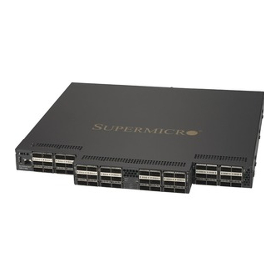
OPA 100G 48-Port Top-of-Rack Switch
Power Cords – 2
•
Rack-mounting kit (two brackets and eight M4 screws)
•
•
USB 2.0 Type A male to Type A male serial console cable
•
Quick Installation Guide
I
S
NSTALL THE
WITCH
Following your rack plan, mark the holes in the rack where the
switch will be installed. One person should lift the switch into the
rack so that it is aligned with the marked holes. A second person
should secure the switch in the rack, using four rack-mounting
screws (not provided).
Caution: Installing the switch in a rack requires two people.
One person should position the switch in the rack, while the
other secures it using the rack screws.
C
P
ONNECT
OWER
Install power modules, then power on. The switch supports up to
two PSUs.
Note: Install power modules before connecting power cords.
Disconnect power cords before removing power modules
Note: For electrical safety purposes, please pay attention to the
following warning notices, printed on the switch unit:
Warning: Disconnect the power cord from all power sources to
completely remove power from the device.
Warning: If the installation requires a different power cord than
the one supplied with the device, make sure you use a power
cord displaying the mark of the safety agency that defines the
regulations for power cords in your country. The mark is your
assurance that the power cord can be used safely with the
device
V
S
O
ERIFY
WITCH
PERATION
Verify basic switch operation by checking the system LEDs. When
operating normally, the PSU1/PSU2 and Mod Status should all be on
green.
PSU1 LED
Mod Status LED
M
I
C
C
AKE
NITAL
ONFIGURATION
HANGES
At this point you may need to make a few basic switch configuration
changes by accessing CLI before connecting to the network. The CLI
can be accessed two ways (with optional management card):
1. Using the USB serial port.
2. Through Ethernet port, using Telnet or SSH.
USB Port
For information on initial switch configuration, refer to the Switch
Installation Guide and the Switch User's Guide at
https://www.supermicro.com/manuals/network/SSH-C48Q_Man
agement_GUI_User_Manual.pdf.
C
N
ONNECT
ETWORK
Install one or two universal
AC power modules in the
Connect DAC or AOC cables to the QSFP28 ports. Or first
switch, connect an external
install QSFP28 transceivers and then connect fiber optic cabling
AC power source to the
to the transceiver ports.
modules.
As connections are made, check the port indicators to be sure
the links are valid.
PSU2 LED
Q
I
G
UICK
NSTALLATION
UIDE
SSH-C48Q/C48QM
Ethernet Port
C
ABLE
Advertisement

Subscribe to Our Youtube Channel
Related Manuals for Supermicro SSH-C48QM


Summary of Contents for Supermicro SSH-C48QM
- Page 1 A second person Installation Guide and the Switch User’s Guide at should secure the switch in the rack, using four rack-mounting https://www.supermicro.com/manuals/network/SSH-C48Q_Man screws (not provided). agement_GUI_User_Manual.pdf. Caution: Installing the switch in a rack requires two people.
- Page 2 Law prohibits the use of UL or CSA -certified cables (that have UL/CSA shown on the code) for any other electrical devices Power Supply (auto sensing, hot swappable): than products designated by Supermicro only. 100-127VAC ; 50-60Hz ; 9.5A 200-240 VAC; 50-60Hz; 4.5A...
Need help?
Do you have a question about the SSH-C48QM and is the answer not in the manual?
Questions and answers