
Subscribe to Our Youtube Channel
Related Manuals for Microchip Technology dsPIC33EP128GS806


Summary of Contents for Microchip Technology dsPIC33EP128GS806
- Page 1 Digital Power Plug-In Module (PIM) User’s Guide 2018 Microchip Technology Inc. DS50002761A...
- Page 2 WiperLock, Wireless DNA, and ZENA are trademarks of Microchip Technology Incorporated in the U.S.A. and other countries. SQTP is a service mark of Microchip Technology Incorporated in the U.S.A. Microchip received ISO/TS-16949:2009 certification for its worldwide headquarters, design and wafer fabrication facilities in Chandler and Silicon Storage Technology is a registered trademark of Microchip Tempe, Arizona;...
-
Page 3: Table Of Contents
1.2 Features ......................9 1.2.1 Electrical Characteristics ................10 1.2.2 Analog and Digital Signals ................ 10 1.2.3 dsPIC33EP128GS806 DP PIM – PCB Edge Connector ......10 1.3 UART Communication .................. 11 1.4 Low-Frequency Bode Plot Measurements ........... 11 Appendix A. Board Layout and Schematics.............. 13 A.1 Pinout ...................... - Page 4 Digital Power PIM User’s Guide NOTES: 2018 Microchip Technology Inc. DS50002761A-page 4...
-
Page 5: Preface
Customer Support • Document Revision History DOCUMENT LAYOUT This document describes how to use the dsPIC33EP128GS806 Digital Power PIM as a development tool to emulate and debug firmware on a target board. The document is organized as follows: • Chapter 1. “Overview”... - Page 6 Digital Power PIM User’s Guide CONVENTIONS USED IN THIS GUIDE This manual uses the following documentation conventions: DOCUMENTATION CONVENTIONS Description Represents Examples Arial font: ® Italic characters Referenced books MPLAB IDE User’s Guide Emphasized text ...is the only compiler...
- Page 7 Preface RECOMMENDED READING This user’s guide describes how to use the dsPIC33EP128GS806 Digital Power PIM. Other useful document(s) are listed below. The following Microchip document(s) are recommended as supplemental reference resources. • “dsPIC33EPXXXGS70X/80X Family Data Sheet” (DS70005258) and is available for download from the Microchip website (www.microchip.com) THE MICROCHIP WEBSITE Microchip provides online support via our website at www.microchip.com.
- Page 8 Digital Power PIM User’s Guide NOTES: 2018 Microchip Technology Inc. DS50002761A-page 8...
-
Page 9: Chapter 1. Overview
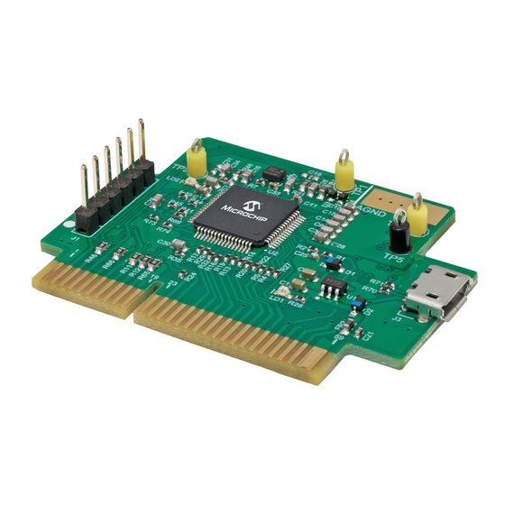
POWER PIM USER’S GUIDE Chapter 1. Overview INTRODUCTION The dsPIC33EP128GS806 Digital Power Plug-In Module (DP PIM) is a demonstration board that showcases the Microchip dsPIC33EP128GS806 16-Bit Digital Signal Controller (DSC) features. The DP PIM provides access to the dsPIC33EP128GS806 analog inputs, the Digital-to-Analog Converter (DAC) outputs, the Pulse-Width Modulation (PWM) outputs and the General Purpose Input and Output (GPIO) ports. -
Page 10: Electrical Characteristics
EMC issues. 1.2.3 dsPIC33EP128GS806 DP PIM – PCB Edge Connector The dsPIC33EP128GS806 DP PIM card has an edge connector compatible with any application board that provides a mating socket. The mating socket type is Samtec, Inc.: MECF-30-01-L-DV-WT. -
Page 11: Uart Communication
Digital Signal Controller (DSC). LOW-FREQUENCY BODE PLOT MEASUREMENTS The dsPIC33EP128GS806 device, with the additional on-board circuitry, is able to perform Bode plot measurements without the need for an isolation transformer. The transformer might be required if the injecting signal tends to be at a very low frequency (for instance, in case of Power Factor Correction (PFC) applications). - Page 12 Digital Power PIM User’s Guide Figure 1-2 Figure 1-3 show measuring procedure examples for plant and closed-loop measurements. FIGURE 1-2: MEASURING PROCEDURE FOR PLANT MEASUREMENT Power Stage Output DAC1 Bode 100 DAC2 Bode 100 Signal Injec Generator G = 2 ADC1 –...
-
Page 13: Appendix A. Board Layout And Schematics
Analog Input, RC Filtered F = 190 kHz, tr = 1.8 µs slot slot slot slot slot slot slot slot slot slot — — — RC7_GPIO Digital General Purpose 270R series resistance SPI_MISO 2018 Microchip Technology Inc. DS50002761A-page 13... - Page 14 Digital Power PIM User’s Guide TABLE A-1: PINOUT AND ELECTRICAL PARAMETERS (CONTINUED) Edge Device Name Connector Function/Description Remark RD0_GPIO Digital General Purpose 270R series resistance RD14_GPIO Digital General Purpose 270R series resistance RC5_GPIO Digital General Purpose 270R series resistance...
-
Page 15: Board Schematics
BOARD SCHEMATICS Figure A-1 Figure A-2 show the board schematics. FIGURE A-1: dsPIC33EP128GS806 DIGITAL POWER PIM SCHEMATIC REV. 1.1 (PAGE 1 OF 2) RA0_AN0_IN MCLR RA0_AN0 MCLR RA1_AN1 150R RA2_AN2 560 pF 0603 RA3_PWM1L RB8_SDA 0603 +3.3V RA4_PWM1H RB15_SCL RB0_AN3... - Page 16 FIGURE A-2: dsPIC33EP128GS806 DIGITAL POWER PIM SCHEMATIC REV. 1.1 (PAGE 2 OF 2) USB/UART-I C interface +5V_USB +5V_USB +5V_USB USB 2.0 MICRO-B FEMALE +3.3V +3.3V 4.7k 4.7k Micro-AB Receptacle 0402 0402 0402 1 2 3 4 5 0402 UART RX...
-
Page 17: Pcb Layout
PCB LAYOUT The dsPIC33EP128GS806 DP PIM is a four-layer FR4, 1.55 mm, Plated Through-Hole (PTH) PCB construction. Figure A-3 through Figure A-5 illustrate the PCB layers and Figure A-6 shows the assembly drawings of the dsPIC33EP128GS806 DP PIM. FIGURE A-3:... - Page 18 FIGURE A-4: dsPIC33EP128GS806 DIGITAL POWER PIM MID1 AND MID2 INNER COPPER (BOTTOM VIEW) Mid1 Inner Copper Mid2 Inner Copper...
- Page 19 FIGURE A-5: dsPIC33EP128GS806 DIGITAL POWER PIM BOTTOM COPPER AND BOTTOM SILKSCREEN (BOTTOM VIEW) Bottom Copper Bottom Silkscreen...
- Page 20 FIGURE A-6: dsPIC33EP128GS806 DIGITAL POWER PIM TOP AND BOTTOM ASSEMBLY Top Assembly Bottom Assembly...
-
Page 21: Appendix B. Bill Of Materials (Bom)
DIGITAL POWER PIM USER’S GUIDE Appendix B. Bill of Materials (BOM) This appendix contains the Bill of Materials (BOM) for the dsPIC33EP128GS806 Digital Power PIM. • Bill of Materials BILL OF MATERIALS Table B-1 shows the Bill of Materials for the dsPIC33EP128GS806. - Page 22 Digital Power PIM User’s Guide TABLE B-1: dsPIC33EP128GS806 DIGITAL POWER PIM BILL OF MATERIALS (CONTINUED) Qty. Designator Description Manufacturer Manufacturer Part Number ® Diode LED Green, 2V, Lite-On , Inc. LTST-C190KGKT 30 mA, 35 mcd, Clear, SMD, 0603 Diode LED Red, 1.8V, Lite-On, Inc.
- Page 23 Bill of Materials (BOM) TABLE B-1: dsPIC33EP128GS806 DIGITAL POWER PIM BILL OF MATERIALS (CONTINUED) Qty. Designator Description Manufacturer Manufacturer Part Number Microchip Parts Microchip Analog LDO, 3.3V, Microchip MCP1755T-3302E/OT MCP1755T-3302E/OT, Technology Inc. SOT-23-5 Microchip MCU, 16-Bit, Microchip dsPIC33EP128GS806-I/PT 120 MHz, 128K, 8K, Technology Inc.
-
Page 24: Worldwide Sales And Service
New York, NY Tel: 46-31-704-60-40 Tel: 631-435-6000 Sweden - Stockholm San Jose, CA Tel: 46-8-5090-4654 Tel: 408-735-9110 UK - Wokingham Tel: 408-436-4270 Tel: 44-118-921-5800 Canada - Toronto Fax: 44-118-921-5820 Tel: 905-695-1980 Fax: 905-695-2078 2018 Microchip Technology Inc. DS50002761A-page 24 10/25/17...
Need help?
Do you have a question about the dsPIC33EP128GS806 and is the answer not in the manual?
Questions and answers