
Related Manuals for CAME ATS30DGS


Summary of Contents for CAME ATS30DGS
- Page 1 Gearmotor for swing gates FA01338-EN ATS30DGS ATS50DGS ATS30DGR English INSTALLATION MANUAL...
- Page 3 Machinery Directive (2006/42/EC) and with the reference harmonised technical standards are specified in the general CAME product catalogue or on the website www.came.com. • Make sure the mains power supply is disconnected during all installation procedures. • Check that the temperature ranges given are suitable for the installation site. • The appliance must be powered with a voltage corresponding to the value shown on the rating plate.
-
Page 4: Dismantling And Disposal
DISMANTLING AND DISPOSAL CAME S.p.A. employs an Environmental Management System at its premises. This system is certified and compliant with the UNI EN ISO 14001 standard to ensure that the environment is respected and safeguarded. Please continue safeguarding the environment. At CAME we consider it one of the fundamentals of our operating and market strategies. -
Page 5: Intended Use
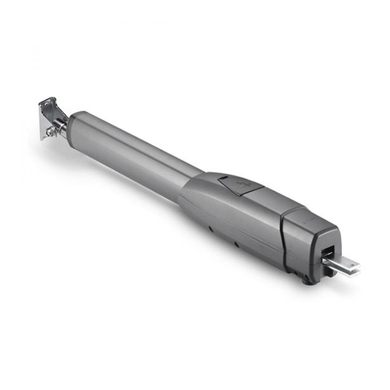
Description 801MP-0070 ATS30DGS - Irreversible telescopic gearmotor 24 V with encoder for swing gates with Max. C up to 200 mm with leaf up to 3 m and 400 kg. Grey RAL7024. 801MP-0080 ATS50DGS - Irreversible telescopic gearmotor 24 V with encoder for swing gates with Max. C up to 200 mm with leaf up to 5 m and 400 kg. Grey RAL7024. - Page 6 Size 1320 ATS30DGS ATS30DGR 1550 1050 ATS50DGS Usage limitations MODELS ATS30DGS ATS50DGS ATS30DGR Gate-leaf length (m) Gate-leaf weight (Kg) 1000 For leaves longer than 2.5 m, install an electric lock. Technical data MODELS ATS30DGS ATS50DGS ATS30DGR Motor power supply (V)
-
Page 7: Installation
INSTALLATION The following illustrations are examples only. The space available for fitting the operator and accessories varies depending on the area where it is installed. It is up to the installer to find the most suitable solution. The drawings refer to a gearmotor installed on the left-hand side. Preliminary operations Prepare the junction boxes and corrugated tubes you need for the connections from the junction pit. - Page 8 Manually open the gate leaf to 90° or 120°. First determine where the gate bracket needs to be positioned, then where the post bracket needs to be positioned. Respect the values indicated in the table. ≥60 ATS30DGS ATS30DGR Gate-leaf opening (°) Max. C 90°...
-
Page 9: Fastening The Brackets
Fastening the brackets Secure the post bracket with plugs and screws. The holes on the bracket fixing plate allow you to vary the opening angle of the gate leaf. Fasten in place with screws or weld the bracket to the gate. ø... - Page 10 Fastening the gearmotor Lubricate all moving parts on the operator. The self-locking nut must be loosely tightened so as not to affect the movement of the telescopic arm with the gate bracket. ATS30DGR...
-
Page 11: Electrical Connections
ELECTRICAL CONNECTIONS Before working on the control panel, disconnect the mains power supply and remove the batteries, if any. Remove the protective cover to access the terminal board. Control panel Gearmotor delayed while opening Gearmotor delayed while closing 230 V AC - 50-60 HZ power supply input Yellow/green cable M N ENC M N ENC... - Page 12 Determining the end-of-travel points with micro limit switches Rod for determining the opening end-of-travel point Rod for determining the closing end-of-travel point Micro limit switches The micro switches are positioned at the far ends of the travel range. To move the microswitch 10 mm in either direction, turn the rod 20 times. Determining the opening end-of-travel points Release the gearmotor.
- Page 13 Close the gate manually. First determine where the gate bracket needs to be positioned, then where the post bracket needs to be positioned. Respect the values indicated in the table. Additional bracket (not included) ATS30DGS ATS30DGR Gate-leaf opening (°) 90°...
- Page 14 Electrical connections Before working on the control panel, disconnect the mains power supply and remove the batteries, if any. Remove the protective cover to access the terminal board. Control panel Gearmotor delayed while opening Gearmotor delayed while closing 230 V AC - 50-60 HZ power supply input Yellow/green cable M1 N1 ENC1 M2 N2 ENC2...
- Page 15 Determining the end-of-travel points with micro limit switches Rod for determining the closing end-of-travel point Rod for determining the opening end-of-travel point Determining the opening end-of-travel points Release the gearmotor. Open the gate manually. Send an opening command. At the same time, turn the rod for determining the opening end-of-travel point ANTICLOCKWISE until the gearmotor stops. Leave the rod nut loose to determine the end-of-travel points.
-
Page 16: Final Operations
FINAL OPERATIONS... - Page 17 MCBF Models ATS30AGS-ATS30AGR ATS50AGS-ATS50AGR 2 m - 800 kg 120000 2.5 m - 600 kg 110000 3 m - 400 kg 100000 2 m - 1000 kg 120000 2.5 m - 800 kg 110000 3 m - 600 kg 100000 4 m - 500 kg 85000 5 m - 400 kg...
- Page 20 CAME S.p.A. Via Martiri della Libertà, 15 31030 Dosson di Casier Treviso - Italy Tel. (+39) 0422 4940 Fax (+39) 0422 4941...
Need help?
Do you have a question about the ATS30DGS and is the answer not in the manual?
Questions and answers