Apollo XP95 Installation Manual
Output unit
Hide thumbs
Also See for XP95:
- Engineering product manual (25 pages) ,
- Installation manual (18 pages) ,
- Quick start manual (5 pages)
Table of Contents
Advertisement
Quick Links
Functional Test Data
Output Bit
Function
2
NOT USED
1
NOT USED
0
OPERATES RELAY
1 =
ON
0 =
OFF
For further information on protocol bit usage refer to the XP95 Output PIN sheet, PP2018.
Troubleshooting
Before investigating individual units for faults, it is very important to check that the system wiring is fault free.
Earth faults on a data loop or any ancillary zone wiring may cause communication errors.
Many fault conditions are the result of simple wiring errors. Check all connections to the unit and make sure
that the correct value resistors are fitted where necessary.
Fault finding
Problem
No response or missing
Relay fails to operate
Relay energised continuously
Apollo Fire Detectors Limited, 36 Brookside Road, Havant, Hants, PO9 1JR, UK
Tel +44 (0)23 9249 2412 Fax +44 (0)23 9249 2754
Email: techsales@apollo-fire.co.uk Website: www.apollo-fire.co.uk
The part no of this guide is 39214-073/Issue 3
Input Bit
Function
2
NOT USED
1
NOT USED
0
NOT USED
Possible Cause
Incorrect address setting
Incorrect loop wiring
Incorrect wiring
Control panel has incorrect cause and effect programming
Incorrect loop wiring
Incorrect address setting
4
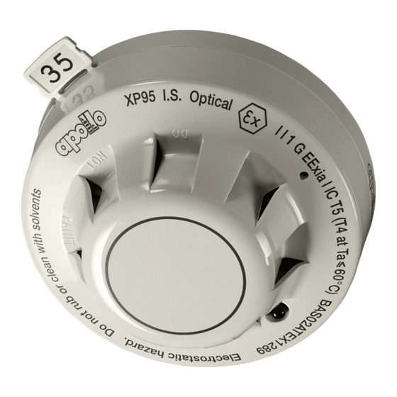
XP95 Output Unit
Installation Guide
General
The XP95 Output Unit, part no 55000-819, is supplied with a backbox for surface mounting. It is also
available without a backbox for flush fitting — part no 55000-817. For flush fitting the installer will need to
provide a suitable metal box with fixing centres of 120.6mm (UK standard 2-gang accessory box).
Note: The XP95 Output Unit is not designed for outdoor use unless it is mounted in a suitable weatherproof
enclosure.
Surface Mounting
1. Mount the backbox as required and install all cables for termination. Ensure that earth continuity is
maintained.
2. Remove the cover plate (if secured) from the Output Unit assembly by inserting the blade of a terminal
screwdriver into each of the four securing clips in turn, gently prising the outer edge of the cover plate
over the clips underneath. DO NOT USE EXCESSIVE FORCE.
3. Terminate all cables.
4. Gently push the completed assembly towards the back box until the mounting holes are aligned and
secure with the two mounting screws provided. DO NOT OVERTIGHTEN.
5. Set the address of the unit as shown on page 3.
6. Finally, when commissioning is complete, fit the cover plate by placing it in position, observing the
correct orientation (LEDs on the PCB must be aligned with viewing holes). Apply pressure to the cover
plate until all four clips are holding it in position.
Flush Mounting
1. Secure a suitable metal back box (30mm minimum depth) in position and install all cables for
termination. Ensure that earth continuity is maintained.
2. Follow steps 2 to 6 as above.
FIRE DETECTORS LIMITED
1
Advertisement
Table of Contents

Related Manuals for Apollo XP95


Summary of Contents for Apollo XP95
-
Page 1: Installation Guide
120.6mm (UK standard 2-gang accessory box). No response or missing Incorrect address setting Incorrect loop wiring Note: The XP95 Output Unit is not designed for outdoor use unless it is mounted in a suitable weatherproof enclosure. Relay fails to operate Incorrect wiring... - Page 2 Commissioning It is important that the XP95 Output Unit be fully tested after installation. An XP95 Test Set, part no 55000- 870, may be used to carry out functional testing of individual units. It can also be used to perform data integrity tests of an entire system.
Need help?
Do you have a question about the XP95 and is the answer not in the manual?
Questions and answers