Table of Contents
Advertisement
Available languages
Available languages
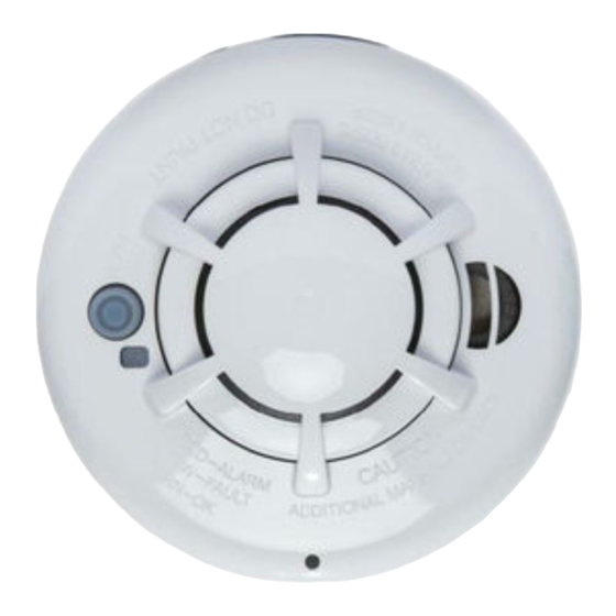
Wireless Smoke Heat Alarm
ATTENTION: This manual should be read prior to use and retained for
further information.
GENERAL INFORMATION
The Wireless Smoke Heat Alarm is a 3xAAA battery powered wireless
detector intended for use with a compatible wireless alarm system. The
detector has a built-in wireless transmitter, which communicates with
the control panel. When smoke is detected, the alarm sounds a loud
local alarm and the built-in transmitter sends a signal to the control
panel. The Wireless Smoke Heat Alarm contains an integrated fixed
41°F temperature freeze sensor that will send a warning signal based on
temperature detected. This detector is designed to provide protection
with 70-foot spacing capability.
The detector can send alarm, tamper and battery condition messages to
the system's receiver. Refer to the wireless system's instruction for the
maximum number of transmitters that can be supported.
CONTENTS OF BOX:
• Wireless Smoke Heat Alarm with base
• Installation guide (APD0601)
• Pack of screws and anchors
• Labels or decals as appropriate
• 3 AAA PC2400 Duracell Procell batteries (1.5V 1100mAh) or 3 AAA
Energizer E92 batteries (1.5V 1100mAh)
51000-355
Installation Guide
Advertisement
Table of Contents

Related Manuals for Apollo 51000-355


Summary of Contents for Apollo 51000-355
-
Page 1: Installation Guide
51000-355 Wireless Smoke Heat Alarm Installation Guide ATTENTION: This manual should be read prior to use and retained for further information. GENERAL INFORMATION The Wireless Smoke Heat Alarm is a 3xAAA battery powered wireless detector intended for use with a compatible wireless alarm system. The detector has a built-in wireless transmitter, which communicates with the control panel. - Page 2 Sounder Status LEDs (do not pulse the sounder and LED concurrently) Normal Green flash every 12 seconds Heat Alarm Red flash every 1 second ANSI S3.41 temporal 3 Heat Test Red flash every 1 second ANSI S3.41 temporal 3 Smoke Alarm Red flash every 1 second ANSI S3.41 temporal 3 (press button to hush...
-
Page 3: Battery Installation And Replacement
tains an integrated fi xed 41°F rm, a message is also sent to the control panel and the detector’s ID 12 hours the panel will display a loss of supervision message. end a warning signal based on played at the console. During an alarm condition, pressing the detec- s designed to provide protection with hush button will silence the sounder (see table below). - Page 4 4. Reinstall the detector onto the mounting base by turning the detector clockwise until the mating marks align. 5. After the power-up sequence the green LED should blink about once every 12 seconds to indicate normal operation. If the batteries are not installed correctly, the detector will not operate and the batteries may be damaged.
- Page 5 be placed on the bottom of the joists. The detector should be positioned Fig 6. Exempl relative to the stairway so as to intercept smoke coming from a fi re in the basement before the smoke enters the stairway. penetrating. In most fires, this dead air space measures about 0.1m Smoke detectors are optional where a door is not provided between living (4in.) along the ceiling from the corner and about 0.1m (4in.) down the room and recreation room (Figure 5).
-
Page 6: Mounting The Detector
• In or below a cupboard • Where air flow would be obstructed by curtains or furniture • Where dirt or dust could collect and block the sensor • Where it could be knocked, damaged, or inadvertently removed This detector shall not be installed in location where the normal ambient temperature is below 40°F (4.4°C) or where it exceeds 100°F (37.8°C). -
Page 7: Maintenance
TESTING THE DETECTOR NOTE: Before testing, notify the central station that the detector system is undergoing maintenance in order to prevent unwanted alarms. Testing the detector will activate an alarm and send a signal to the panel. Also, the test function cannot be used if the detector has a trouble condition. Detectors must be tested after installation and following periodic maintenance. -
Page 8: Safety Tips
WARNING: PLEASE READ CAREFULLY AND THOROUGHLY • NFPA 72 states: Fire-warning equipment for residential occupancies are capable of protecting about half of the occupants in potentially fatal fires. Victims are often intimate with the fi re, too old or too young, or physically or mentally impaired such that they cannot escape even when warned early enough that escape should be possible. -
Page 9: If The Alarm Sounds
• Know at least two ways out of every room, if possible. Make sure all doors and windows leading outside open easily. • Have an outside meeting place (like a tree, light pole or mailbox) a safe distance from the home where everyone should meet. • Practice your home fire drill at night and during the day with everyone in your home, twice a year. - Page 10 interference that may cause undesired operation of the device. This equipment has been tested and found to comply with the limits for a Class B digital device, pursuant to Part 15 of FCC Rules. These limits are designed to provide reasonable protection against harmful interference in a residential installation.
- Page 11 In typical single level and multilevel dwelling units and apartment buildings having similar smoke alarm systems there is a possibility that signals sent by wireless sensors may be blocked or reflected by metal before they reach the alarm Control Panel, even if the signal path has been recently checked during a weekly test.
-
Page 12: Renseignements Généraux
51000-355 Détecteur de chaleur et de fumée sans fil Guide d'installation ATTENTION : Vous devez lire ce manuel avant de l'utiliser et le conserver pour les références futures. RENSEIGNEMENTS GÉNÉRAUX Le détecteur de chaleur et de fumée sans fil est un détecteur sans fil alimenté... - Page 13 Sonde État (n'appuyez pas simultanément sur la sonde et la DEL) Normal Clignote en vert toutes les 12 secondes Désactivé Détecteur de chaleur Clignote en rouge chaque seconde ANSI S3.41 temporel 3 Épreuve de résis- Clignote en rouge chaque se- ANSI S3.41 temporel 3 tance à...
- Page 14 tains an integrated fi xed 41°F rm, a message is also sent to the control panel and the detector’s ID 12 hours the panel will display a loss of supervision message. end a warning signal based on played at the console. During an alarm condition, pressing the detec- s designed to provide protection with hush button will silence the sounder (see table below).
- Page 15 4. Réinstallez le détecteur sur la base de montage en tournant le détecteur dans le sens horaire jusqu’à ce que les repères soient alignés. 5. Après la mise sous tension, la DEL verte devrait clignoter une fois toutes les 12 secondes environ, pour indiquer un fonctionnement normal. Si les piles ne sont pas correctement installées, le détecteur ne fonctionnera pas et les piles risquent d'être endommagées.
- Page 16 be placed on the bottom of the joists. The detector should be positioned Fig 6. Exempl relative to the stairway so as to intercept smoke coming from a fi re in the basement before the smoke enters the stairway. d’air où la fumée peut difficilement pénétrer. Dans la plupart des incendies, cet Smoke detectors are optional where a door is not provided between living room and recreation room (Figure 5).
- Page 17 • À l'intérieur ou sous un placard • Dans des endroits où la circulation d'air serait obstruée par des rideaux ou des meubles • Dans un endroit où de la saleté ou de la poussière pourrait s'accumuler et bloquer le détecteur • Dans un endroit où...
- Page 18 TESTER LE DÉTECTEUR REMARQUE : Avant le test, informez le poste central que le système du détecteur est en maintenance afin d’empêcher des alarmes superflues. Le test du détecteur active une alarme et envoie un signal au panneau. Par ailleurs, la fonction de test ne peut pas être utilisée si le détecteur est en panne.
-
Page 19: Consignes De Sécurité
AVERTISSEMENT : LIRE ATTENTIVEMENT ET MINUTIEUSEMENT • La norme NFPA 72 stipule : Un équipement d’alerte incendie pour locaux d'habitation est capable de protéger environ la moitié des occupants des incendies potentiellement mortels. Les victimes sont souvent proches de l’incendie, trop âgées ou trop jeunes, présentent des déficiences physiques ou mentales, de telle façon qu’elles ne peuvent pas s’échapper, même si elles sont averties suffisamment tôt pour qu’une évacuation soit possible. -
Page 20: Spécifications
• Retenez au moins deux sorties de chaque pièce, si possible. Assurez-vous que toutes les portes et fenêtres qui mènent dehors s’ouvrent facilement. • Ayez un point de rencontre à l’extérieur (comme un arbre, un lampadaire ou une boîte aux lettres) à distance sûre de la maison, où tout le monde devrait se rencontrer. • Pratiquez votre exercice d’incendie familial pendant la nuit et pendant le jour avec tout le monde dans votre maison, deux fois par an. - Page 21 nuisibles, et (2) cet appareil doit accepter toute interférence reçue, y compris les interférences pouvant causer un fonctionnement inopiné de l’appareil. Cet équipement a été testé et déclaré conforme aux limites applicables aux périphériques numériques de classe B, selon la partie 15 de la réglementation de la FCC.
- Page 22 été récemment vérifié au cours d'un test hebdomadaire. Un blocage peut se produire si un objet métallique a été déplacé dans le parcours du signal du capteur. Apollo America 25 Corporate Drive Auburn Hills, MI 48326...
Need help?
Do you have a question about the 51000-355 and is the answer not in the manual?
Questions and answers