Advertisement
Table of Contents
39214-118/Rev 6A
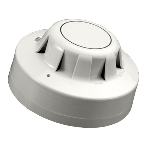
Series 65A Smoke & Heat Detectors
Installation Instructions
General
These instructions apply to the 4" mounting base, part no 45681-200, the 6" mounting base,
part no 45681-220, the low profi le base, part no 45681-232 and the 6" E-Z Fit base, part no
45681-251, for installing Series 65A smoke and heat detectors.
Installation
These products must be installed in accordance with the applicable NFPA standards, local
codes and jurisdictional authorities. Failure to follow these instructions may result in failure
of the detectors to report an alarm condition. Apollo Fire Detector Limited is not responsible
for detectors which are improperly installed, maintained and tested.
Before installing these products check the continuity, polarity and insulation resistance of
all wiring. Check that siting is in accordance with the fi re system drawings and conforms to
all applicable local codes such as NFPA 72.
Use 3" octagonal box for direct connection to the base. 4" octagonal and 4" square boxes
may be used with proper UL listed mounting brackets. When mounting on a wall, install 4" to
12" from the ceiling. Use 3M Weatherban 606 Non-Flammable sealing compound (or equiv-
alent) to seal fi eld wiring conduit opening in the electrical box, this will reduce the stacking
effect. Secure the base to the electrical box with appropriate screws. Do not overtighten
the screws. The raised mark on the side of the base indicates the direction of the detector
LED when fi tted. Connect the shield, if required, to the SHIELD terminal on the base.
©Apollo Fire Detectors Ltd 1994–2011
Apollo Fire Detectors Ltd, 36 Brookside Road, Havant, Hants, PO9 1JR, UK
Tel +44 (0)23 9249 2412 Fax +44 (0)23 9249 2754
Email: techsales@apollo-fi re.co.uk Website: www.apollo-fi re.co.uk
In the USA: Apollo America, 821 Ulrich Ave, Louisville, KY 40219, USA
Tel: (502) 964-6565 Fax: (502) 964-6229
Email: infoUSA@apollo-fi re.com Website: www.apollo-fi re.com
4
1
Advertisement
Table of Contents

Related Manuals for Apollo 65A Series


Summary of Contents for Apollo 65A Series
-
Page 1: Installation Instructions
These products must be installed in accordance with the applicable NFPA standards, local codes and jurisdictional authorities. Failure to follow these instructions may result in failure of the detectors to report an alarm condition. Apollo Fire Detector Limited is not responsible for detectors which are improperly installed, maintained and tested. - Page 2 (11ºC) below rating (70ºC) (60ºC) Fig 2 Wiring diagram of Series 65A zone with common remote indicator Control Panel Refer to www.apollo-fi re.co.uk for compatible panels The above instructions cover the following base model: 45681-200 4" mounting base 45681-220 6" mounting base 45681-232 low profi...
Need help?
Do you have a question about the 65A Series and is the answer not in the manual?
Questions and answers