Advertisement
© Apollo Fire Detectors Limited 2014
Apollo Fire Detectors Limited, 36 Brookside Road, Havant, Hampshire, PO9 1JR, UK
Tel: +44 (0) 23 9249 2412 Fax: +44 (0) 23 9249 2754
Email: techsales@apollo-fi re.co.uk Website: www.apollo-fi re.co.uk
39214-394/Issue 6
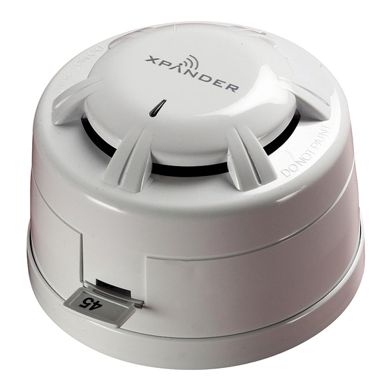
XPander Smoke and Heat Detectors
General
Do not install any XPander equipment until a full site survey has been completed using the
XPander site survey tool. A maximum of 5 interfaces are permitted for each site. For sites
that require more than 5 interfaces please contact Apollo. All installation engineers must
have had certifi ed XPander training.
The XPander smoke and heat detector variants are available under the following part
numbers:
Complete Units
Part Number
XPA-CB-12034-APO
XPA-CB-13032-APO
XPA-CB-11170-APO
XPA-CB-11171-APO
Spares
Part Number
XPA-WB-10022-APO
XPA-OP-12034-APO
XPA-OH-13023-APO
XPA-HT-11170-APO
XPA-HT-11171-APO
The installation must conform to BS5839-1:2013 (or applicable local codes). All detectors are
suitable for indoor use only.
Installation
All detectors must be sited in accordance with the original approved design and site
survey details. Where practical the detector's LED should face towards the room's
entrance.
1.
Twist the ceiling mounting plate anti-clockwise to remove it from the mounting base.
2.
The ceiling mounting plate must be fi tted using both mounting holes and suitable
fi xings or fasteners (see Fig. 1).
Note: Any screw heads must be fl ush or semi fl ush with the internal surface of the ceiling
mount otherwise the battery PCB may be damaged.
3.
Attach the mounting base to the ceiling mounting plate ensuring the tamper switch
spring assembly makes contact. Locate the three lugs and twist clockwise.
4.
Fit the detector to the mounting base.
5.
Fit the power jumper shorting link and commission the unit according to the XPander
commissioning guide PP2286.
Installation Guide
Description
XPander Optical detector with base
XPander Multisensor detector with base
XPander Heat A1R detector with base
XPander Heat CS detector with base
Description
XPander Mounting base only
XPander Optical head only
XPander Multisensor head only
XPander Heat A1R head only
XPander Heat CS head only
1
Advertisement
Table of Contents

Related Manuals for Apollo XPANDER Series


Summary of Contents for Apollo XPANDER Series
-
Page 1: Installation Guide
Do not install any XPander equipment until a full site survey has been completed using the XPander site survey tool. A maximum of 5 interfaces are permitted for each site. For sites that require more than 5 interfaces please contact Apollo. All installation engineers must have had certifi ed XPander training. - Page 2 Snip along marked lines and remove this part to lock the detector to the base. © Apollo Fire Detectors Limited 2008/TP © Apollo Fire Detectors Limited 2007 TP Fig 1 Mounting Details Fig 2. Locking Mechanism XPERT Card Insertion and Removal Removal requires access to the inner section of the base.
Need help?
Do you have a question about the XPANDER Series and is the answer not in the manual?
Questions and answers