Sign In
Upload
Manuals
Brands
Tektronix Manuals
Measuring Instruments
TLA 714
Tektronix TLA 714 Manuals
Manuals and User Guides for Tektronix TLA 714. We have
3
Tektronix TLA 714 manuals available for free PDF download: Service Manual, Installation Manual, Instructions Manual
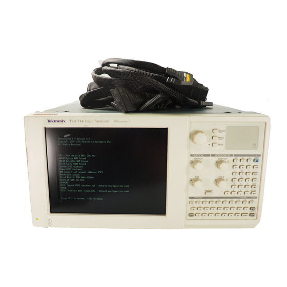
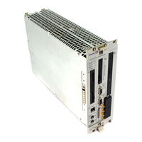
Tektronix TLA 714 Service Manual (159 pages)
Color Portable Mainframe
Brand:
Tektronix
| Category:
Measuring Instruments
| Size: 1 MB
Table of Contents
Service Manual
2
Table of Contents
6
Portable Mainframe
12
Product Description
22
Table 1-1: Internal Controller
23
Characteristics Tables
23
Table 1-2: Display System
24
Table 1-3: Backplane Interface
25
Table 1-4: Front Panel Interface
25
Table 1-5: Rear Panel Interface
26
Specifications
27
Table 1-6: AC Power Source
28
Table 1-7: Secondary Power
28
Table 1-8: Certifications and Compliances: TLA 714 Logic Analyzer Color Portable Mainframe
29
Table 1-10: Environmental
30
Table 1-9: Cooling
30
Figure 1-1: Front and Side Views of the Portable Mainframe
31
Figure 2-1: TLA 714 Portable Mainframe Front Panel
34
Figure 2-2: Portable Mainframe Rear Panel
36
Table 2-2: SVGA out Pin Assignments
37
Table 2-3: LPT (Parallel Interface) Pin Assignments
38
Operating System and Application Interface
39
Installation
34
Table 2-1: USB (Universal Serial Bus) Pin Assignments
35
Table 1-11: Mechanical
31
Theory of Operation
44
Preparation
48
Inspection and Cleaning
49
Removal and Installation Procedures
52
Equipment Required
53
Table 4-1: Tools Required for Part Removal
53
Exploded View
54
Figure 4-1: External Parts
54
Figure 4-2: Depress the Latch
55
Removing the Replaceable Hard Disk Drive
55
Figure 4-4: Removing the Hard Disk Drive Cartridge
56
Figure 4-5: Removing the Hard Disk Drive from the Cartridge
57
Figure 4-6: Trim Ring Removal
58
Figure 4-7: Flat Panel Display Assembly Removal
60
Figure 4-8: Front-Panel Control Assembly Removal
63
Front Panel Knobs
64
CD ROM Drive
65
Bottom Cover
66
Top Cover
67
Figure 4-9: Top and Side Cover Removal
68
Left Side Cover
68
Right Side Cover
69
Line Cord and Line Fuse
70
Figure 4-10: Line Cord and Line Fuse Removal
71
Figure 4-11: Power Supply Removal
72
Power Supply
72
Rear Chassis Fan Tray
73
Figure 4-12: Rear Chassis Fan Tray Removal
74
Individual Fans
75
Figure 4-13: Individual Fan Removal
76
Figure 4-14: Flip Stand and Rear Feet Removal
77
Flip Stands and Rear Feet
77
Cord Wrap Feet
78
Figure 4-15: Cord-Wrap Feet Removal
78
Figure 4-16: Handle Removal
79
Handle
79
Controller Board
80
Procedures for Internal Parts
80
Figure 4-17: Internal Parts
81
Main Memory
82
Backplane Board
83
Front Panel Control Board
83
Figure 4-18: Front Panel Control Assembly Parts Locations
84
Glidepoint Assembly
85
Elastomeric Keypad
86
Floppy Disk Drive
61
Front Panel Control Assembly
62
Figure 4-3: Unlatching the Hard Disk Drive Cartridge
56
Flat Panel Display Assembly
59
Fixed Hard Disk Drive Removal and Installation
88
General Instructions
89
Preparation
89
Tools Required
89
Figure 4-19: Removing the Hard Disk Drive from the Cartridge
90
Remove Hard Disk Drive from the Cartridge
90
Figure 4-20: Depress the Latch
91
Removing the Replaceable Hard Disk Drive
91
Figure 4-22: Removing the Hard Disk Drive Cartridge
92
Figure 4-23: Front Cover and Trim Ring Removal
93
Figure 4-24: Flat Panel Display Assembly Removal
95
Install Fixed Hard Disk Drive
96
Figure 4-25: Installing the Fixed Hard Disk Drive
97
Install Flat Panel Display Assembly
98
Install the Trim Ring
98
Verify Operation
98
Figure 4-21: Unlatching the Hard Disk Drive Cartridge
92
Remove Flat Panel Display Assembly
94
Remove the Trim Ring
93
Troubleshooting
100
Service Level
100
Check for Common Problems
101
Table 4-2: Failure Symptoms and Possible Causes
101
Eliminate Other Problem Sources
103
Equipment Required
103
Fault Isolation Procedure
103
Troubleshoot the Portable Mainframe
103
Figure 4-26: Primary Troubleshooting Tree
104
Figure 4-27: Jumper Locations for Bypassing Front Panel Control Assembly
107
Figure 4-28: Location of J1 and J2 Pins Within the Portable
109
Table 4-5: Command Line Options for Resman32
110
Figure 4-29: Resman32 Program Output
111
BIOS Setup Error Messages
112
Table 4-6: BIOS Error Codes and Explanations
112
Update the BIOS Version
114
Adjustment after Repair
115
TLA 700 Startup Sequence
115
Figure 4–30: TLA 700 Startup Sequence
116
Table 4-4: Power Supply Voltages and Backplane Connector Pins
108
Isolating System Problems
109
Controller and PC Diagnostics
105
Power-On Diagnostics
105
Table 4-3: TLA 700 Power-On Diagnostic Tests
105
Qa+Win32
106
Bypassing Front Panel Controls
107
Checking the Power Supply Voltages
107
Repackaging Instructions
118
Packaging
118
Shipping to the Service Center
118
Mainframe
122
Table 5-1: Portable Mainframe Options and Upgrade Kits
122
Tektronix Options
122
Service Options
123
Table 5-2: Power Cord Identification
124
Interconnection Block Diagram
128
Figure 6–2: Portable Mainframe Block Diagram
129
Table 7-1: Standard Accessories
132
Table 7-2: Standard Accessories
133
Optional Accessories
133
Using the Replaceable Parts List
134
Table 7-3: Parts Lists Column Descriptions
135
Figure 7–1: External Parts
140
Figure 7–2: Front Panel Assembly
142
Figure 7–3: Floppy Disk Drive, Front Panel Interface Board, and Related Cables
144
Figure 7–4: Controller Board and EMI Shield
146
Figure 7–5: Power Supply and Fan
148
Advertisement
Tektronix TLA 714 Installation Manual (83 pages)
Logic Analyzer
Brand:
Tektronix
| Category:
Test Equipment
| Size: 2 MB
Table of Contents
Table of Contents
6
General Safety Summary
10
Service Safety Summary
12
Preface
14
TLA700 Series Logic Analyzers
14
Figure II: TLA721 Benchtop Mainframe with a TLA7XM Expansion Mainframe
15
Related Documentation
16
Table I: Tektronix Logic Analyzer Family Documentation
16
Contacting Tektronix
17
Basic Installation
18
Check the Shipment
18
Environmental Considerations
18
TLA715 Portable Mainframe Site Considerations
19
TLA721 Benchtop Mainframe and TLA7XM Expansion Mainframe Site Considerations
19
Installing TLA7XM Expansion Mainframes
19
Install the Expansion Module
19
Figure 1: TLA721 Benchtop Mainframe with One TLA7XM Expansion Mainframe
20
Figure 2: TLA721 Benchtop Mainframe with Two TLA7XM Expansion Mainframes
21
Figure 3: TLA715 Portable Mainframe with Two TLA7XM Expansion Mainframes
21
Install the Expansion Cables
22
Chassis Ground Connections
23
Figure 4: Location of the Ground Connection on the TLA700 Logic Analyzers
23
Installing TLA700 Modules
24
Logical Address Switches
24
Merging Modules
25
Installing Modules in the TLA715 Portable Mainframe
25
Figure 5: Logical Address Switches (Set to Address FF)
25
Mainframe
26
Figure 6: Installing Modules
27
Module Keys
28
Figure 7: Module Keys
28
Covering Empty Slots
29
Figure 8: Installing Panel Covers on the TLA715 Portable Mainframe
29
Figure 9: Installing Panel Covers on the TLA721 Benchtop Mainframe
29
Connecting Accessories
30
Connecting Accessories to the TLA700 Series
30
Figure 10: TLA700 Series Accessories Connections
30
Additional Accessory Connection Information
31
Connecting Probes
31
Table 1: Additional Accessory Connection Information
31
Connecting Probes to the Logic Analyzer Module
32
Figure 11: Connecting the P68Xx or P69Xx Logic Analyzer Probes to the Tla7Nax Logic Analyzer Module
32
Figure 12: Connecting the P68Xx or P69Xx Logic Analyzer Probes to the Tla7Axx Logic Analyzer Module
33
Configuring and Connecting the Pattern Generator Probes
34
Figure 13: Connecting the P64Xx Logic Analyzer Probes to the Tla7Lx/MX/Nx/Px/Qx Logic Analyzer Modules
34
First Time Operation
35
Turning the Logic Analyzer on
35
Table 2: TLA700 Series Line Fuses
35
Figure 14: Line Fuse and Power Cord Connector Locations
36
Turning on the TLA7XM Expansion Mainframes
37
Turning off the Mainframes
37
Performing the Incoming Inspection
37
Figure 15: TLA700 On/Standby Switch Locations
37
Checking Logic Analyzer Probes (Optional)
38
Checking the P624X Oscilloscope Probes (Optional)
39
Checking the P647X Pattern Generator Probes (Optional)
39
Checking the TLA700 Mainframe (Optional)
39
Backing up User Files
39
Removing the Replaceable Hard Disk Drive
39
Connecting Probes to the Target System
40
Figure 16: Accessing the TLA700 Replaceable Hard Disk Drive
40
Additional Information
41
Merging TLA700 Modules
42
Logic Analyzer Merging Rules
42
TLA7PG2 Pattern Generator Module Merging Rules
43
Merge Procedure
43
Merging Tla7Axx/Tla7Nax Logic Analyzer Modules
44
Figure 17: Location of Modules in a Merged System
44
Figure 18: Removing the Merger Connector Assembly from the Module
45
Figure 19: Connecting Modules in a Merged Set
46
Figure 20: Installing the Merged Module Set in the Mainframe
47
Unmerging Tla7Axx/Tla7Nax Logic Analyzer Modules
48
Merging Tla7Lx/MX/Nx/Px/Qx Logic Analyzer Modules
49
Two-Way Logic Analyzer Merge Procedure
49
Figure 21: Removing the Cover
50
Figure 22: Feeding the Merge Cable through the Cover
51
Figure 23: Seating the Cover on the Chassis
52
Figure 24: Lining up the Two Modules
53
Three-Way Logic Analyzer Merge Procedure
54
Storing the Logic Analyzer Module Merge Cable
54
Product Overview
56
Front Panel Controls
56
TLA700 Series External Connectors
56
Restoring and Reinstalling Software
58
Reinstalling the Hard Disk Image
58
Backing up Files
58
Installing the Operating System and TLA Application Software
59
Table 3: TLA User File Suffixes
59
Table 4: Bios Boot Settings for Reinstalling Software from the
60
Reinstalling the TLA Application Software and the Pattern Generator Application Software
62
Installing the TPI or PPI Remote Operation Software
63
Installing the Tlavu and Patgenvu Software on a PC
64
Upgrading or Restoring Firmware
65
Upgrading Firmware on Tla7Axx/Tla7Nax Logic Analyzer Modules
65
Upgrading Firmware on Tla7Lx/MX/Nx/Px/Qx/DX/7Ex Modules
67
Table 5: TLA Firmware Files
69
Upgrading Firmware on the TLA7PG2 Pattern Generator Modules
70
Appendix A: TLA721 Mainframe Power Information
72
Table 6: Power for Instrument Modules
72
Appendix B: User Service Procedures
76
Service Offerings
76
Warranty Repair Service
76
Calibration and Repair Service
76
General Care
76
Preventive Maintenance
77
Cleaning the Flat Panel Display
77
Exterior Surfaces
77
Floppy Disk Drive
78
In Case of Problems
78
Diagnostics
78
Software Problems
79
Hardware Problems
79
Repacking for Shipment
79
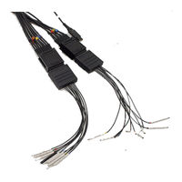
Tektronix TLA 714 Instructions Manual (40 pages)
Logic Analyzer Probes
Brand:
Tektronix
| Category:
Measuring Instruments
| Size: 1 MB
Table of Contents
Table of Contents
5
General Safety Summary
7
Preface
9
Related Documentation
9
Contacting Tektronix
10
Figure 1: P6417 and P6418 Logic Analyzer Probes
11
Operating Basics
11
Product Description
11
Attaching Probe Labels
11
Table 1: Probe Section and Label Combinations
12
Figure 2: Attaching Probe Labels
13
Figure 3: Connecting the Logic Analyzer Probes
14
Connecting the Probes
14
Figure 4: Connecting the Probes to the Target System
15
Figure 5: Probe Footprints
17
Reference
17
Probe Connectors
17
Figure 6: Probe Podlet Clearance
18
Figure 7: Probe Loading
18
Loading and Equivalent Circuits
18
Specifications
19
Table 2: Electrical and Mechanical Specifications
19
Table 3: Environmental Specifications
20
Figure 8: Probe Functional Verification Test Setup
21
Maintenance
21
Functional Check
21
Figure 9: Activity Monitor
23
Inspection and Cleaning
23
P6418 Probe Service Procedures
23
Replacing Podlets on the P6417 Probes
23
Figure 10: Moving Probe Podlets
24
Figure 11: Disassembling the Probe Cable
25
Figure 12: Removing the Faulty Channel from the Probe Cable Header Housing
26
Figure 13: Removing a Podlet Cable from the Rubber Comb
27
Figure 14: Replacing a Podlet in the Podlet Holder
28
Figure 15: Installing the Color-Coded Ring
29
Figure 16: Installing the Cable in the Cable Header Housing
30
Repackaging Instructions
31
Replaceable Parts
33
Parts Ordering Information
33
Using the Replaceable Parts List
33
Figure 17: P6417 and P6418 Probe Accessories
34
Figure 18: P6417 Probe Exploded View
36
Figure 19: P6418 Probe Exploded View
37
Advertisement
Advertisement
Related Products
Tektronix TLA715 Series
Tektronix TLA 711
Tektronix TLA7AA1
Tektronix TLA7AA2
Tektronix TLA7AA4
Tektronix TLA7AC2
Tektronix TLA7AA3
Tektronix TLA7AC4
Tektronix TLA7N2
Tektronix TLA7P2
Tektronix Categories
Test Equipment
Measuring Instruments
Amplifier
Portable Generator
Printer
More Tektronix Manuals
Login
Sign In
OR
Sign in with Facebook
Sign in with Google
Upload manual
Upload from disk
Upload from URL