Table of Contents
Advertisement
Advertisement
Table of Contents

Related Manuals for Peak PCAN-USB FD


Summary of Contents for Peak PCAN-USB FD
- Page 1 PCAN-USB FD User Manual User Manual 1.5.0 © 2021 PEAK-System Technik GmbH...
-
Page 2: Imprint
IPEH-004022 Imprint PCAN® is a registered trademark of PEAK-System Technik GmbH. CANopen®, CANopen FD® and CiA® are registered EU trademarks of CAN in Automation e.V. Other product names in this document may be the trademarks or registered trademarks of their respective companies. They are not explicitly marked by ™... -
Page 3: Table Of Contents
4.3 Distinguishing Several PCAN-USB FD Adapters 5 Software and API 5.1 Monitor Software PCAN-View 5.1.1 Receive/Transmit Tab 5.1.2 Trace Tab 5.1.3 PCAN-USB FD Tab 5.1.4 Bus Load Tab 5.1.5 Error Generator Tab 5.1.6 Status Bar Contents PCAN-USB FD User Manual 1.5.0 © 2021 PEAK-System Technik GmbH... - Page 4 5.2.1 Features of PCAN-Basic 5.2.2 Principle Description of the API 5.2.3 Notes about the License 6 Technical Specifications Appendix A CE Certificate Appendix B Dimension Drawings Appendix C Quick Reference Contents PCAN-USB FD User Manual 1.5.0 © 2021 PEAK-System Technik GmbH...
-
Page 5: Introduction
Quick Reference with brief information about the installation and operation of the PCAN-USB FD adapter. 1.1 Properties at a Glance Adapter for High-speed USB 2.0 (compatible to USB 1.1 and USB 3.0) High-speed CAN connection (ISO 11898-2) 1 Introduction PCAN-USB FD User Manual 1.5.0 © 2021 PEAK-System Technik GmbH... -
Page 6: System Requirements
System Requirements A vacant USB port (USB1.1, USB 2.0 or USB 3.0) at the computer or at a self- powered USB hub connected to the computer 1 Introduction PCAN-USB FD User Manual 1.5.0 © 2021 PEAK-System Technik GmbH... -
Page 7: Scope Of Supply
Operating system Windows 10, 8.1 (32/64-bit) or Linux (32/64-bit) Note: Do not use a USB extension cable to connect the PCAN-USB FD adapter to the computer. The use of an exten- sion cable does not comply with the USB specification and can lead to malfunction of the adapter. -
Page 8: Installing The Software And The Adapter
Do the following to connect the adapter: Note: Do not use a USB extension cable to connect the PCAN-USB FD adapter to the computer. The use of an exten- sion cable does not comply with the USB specification and can lead to malfunction of the adapter. -
Page 9: Connecting The Can Bus
CAN connector. Pin 1 is not in use at the delivery state. For more infor- mation see section 3.2 . Tip: Connect a CAN bus with a different transmission standard via a bus converter. PEAK-System offers different bus converter modules like the PCAN-TJA1054 for a Low-speed CAN bus according to ISO 11898-3. - Page 10 1. Open the adapter casing. Push the latches on both sides cautiously, e.g. with a flat tip screwdriver. 2. Remove the board. 3. Set the solder bridge. Figure 2: Top view PCAN-USB FD board, solder field JP4 3 Connecting the CAN Bus PCAN-USB FD User Manual 1.5.0...
-
Page 11: Activating Internal Termination
120 Ohms. Otherwise disturbances may arise. Do the following to activate the internal termination: Attention! Risk of short circuit! Solder with great care to avoid unwanted short circuits on the circuit board. 3 Connecting the CAN Bus PCAN-USB FD User Manual 1.5.0 © 2021 PEAK-System Technik GmbH... - Page 12 LED must be in the corres- ponding hole. 5. Push the bottom part of the casing onto the top part until the latches click in. 3 Connecting the CAN Bus PCAN-USB FD User Manual 1.5.0 © 2021 PEAK-System Technik GmbH...
-
Page 13: Cabling
High-Speed CAN networks may have bit rates of up to 1 Mbit/s. The maximum bus length depends primarily on the bit rate. The following table shows the maximum possible CAN bus length at different bit rates: 3 Connecting the CAN Bus PCAN-USB FD User Manual 1.5.0 © 2021 PEAK-System Technik GmbH... - Page 14 CAN, despite the higher data bit rate of CAN FD. The depen- dency is based on the bit rate during the arbitration, called nominal bit rate. The nominal bite rate at CAN FD can be up to 1 Mbit/s. 3 Connecting the CAN Bus PCAN-USB FD User Manual 1.5.0 © 2021 PEAK-System Technik GmbH...
-
Page 15: Operation
4 Operation Status LED The PCAN-USB FD adapter has a status LED which can be in one of the following conditions: Status Meaning Green There's a connection to a driver of the operating system. Green slow blinking A software application is connected to the adapter. -
Page 16: Software And Api
Figure 5: PCAN-View for Windows PCAN-View is simple Windows software for viewing, transmitting, and logging CAN and CAN FD messages. Note: This chapter describes the use of PCAN-View with a CAN FD adapter. 5 Software and API PCAN-USB FD User Manual 1.5.0 © 2021 PEAK-System Technik GmbH... - Page 17 4. From the drop-down list, select a Nominal Bit rate, which is used for the arbit- ration phase (max. 1 Mbit/s). 5. Enable the Data Bit rate checkbox. 5 Software and API PCAN-USB FD User Manual 1.5.0 © 2021 PEAK-System Technik GmbH...
- Page 18 CAN environment (e.g. due to different bit rates). 9. Confirm the settings in the dialog box with OK. The main window of PCAN-View appears. The following subsections describe elements of the main window. 5 Software and API PCAN-USB FD User Manual 1.5.0 © 2021 PEAK-System Technik GmbH...
-
Page 19: Receive/Transmit Tab
Do the following to transmit a CAN FD message: 1. Select the menu command Transmit > New Message (alternatively |Ins| The New Transmit Message dialog box appears. Figure 8: Dialog box new transmit message 5 Software and API PCAN-USB FD User Manual 1.5.0 © 2021 PEAK-System Technik GmbH... - Page 20 Tip: Under the menu command File > Save, you can save the current transmit messages into a transmit list. Saved transmit lists are available for reuse. 5 Software and API PCAN-USB FD User Manual 1.5.0 © 2021 PEAK-System Technik GmbH...
-
Page 21: Trace Tab
Tracer as soon as the buffer is full. The ring buffer mode overwrites the oldest messages by new ones as soon as the buffer is full. 5 Software and API PCAN-USB FD User Manual 1.5.0 © 2021 PEAK-System Technik GmbH... -
Page 22: Pcan-Usb Fd Tab
The PCAN-USB FD tab contains some detailed information about the hardware and driver. In addition, you can assign a Device ID to the adapter. Thus, it can be uniquely identified while operating several PCAN-USB FD adapters on a computer at the same time. -
Page 23: Bus Load Tab
CAN bus which must be recognized as an error by the connected CAN nodes. You can destroy CAN frames with the error generator by one of two methods: 5 Software and API PCAN-USB FD User Manual 1.5.0 © 2021 PEAK-System Technik GmbH... -
Page 24: Status Bar
5. Confirm the entries with Apply to activate the error generator. 6. Stop destroying further CAN frames with Disable. 5.1.6 Status Bar Figure 13: Display of the status bar 5 Software and API PCAN-USB FD User Manual 1.5.0 © 2021 PEAK-System Technik GmbH... -
Page 25: Linking Own Programs With Pcan-Basic
In the download area of our website www.peak-system.com/quick/DL-Develop-E can find files for the programming interface (API) PCAN-Basic. This API provides basic functions for linking own programs to CAN and CAN FD interfaces by PEAK-System and can be used for the following operating systems: Windows 10, 8.1 (32/64-Bit) Windows CE 6.x (x86/ARMv4) -
Page 26: Features Of Pcan-Basic
Use of a single DLL for all supported hardware types Use of up to 16 channels for each hardware type (depending on the PEAK CAN interface used) Simple switching between channels of a PEAK CAN interface... -
Page 27: Principle Description Of The Api
CAN hardware, up to 16 CAN channels can be opened at the same time. After a successful initialization the CAN channel is ready. No further configuration steps are required. 5 Software and API PCAN-USB FD User Manual 1.5.0 © 2021 PEAK-System Technik GmbH... -
Page 28: Notes About The License
PEAK-System or one of its partners. If a CAN hardware component of third-party suppliers should be compatible to one of PEAK-System, then you are not allowed to use or to pass on the driver software of PEAK-System. If a third-party supplier develops software based on the PCAN-Basic and problems occur during the use of this software, consult the software provider. -
Page 29: Technical Specifications
Time stamp resolution 1 µs D-Sub pin 1; 5 V, max. 50 mA, Supplying external devices Not assigned at delivery Measures Size (w/o cable) 75 x 43 x 22 mm Cable length About 0.75 m Weight (with cable) 68 g 6 Technical Specifications PCAN-USB FD User Manual 1.5.0 © 2021 PEAK-System Technik GmbH... - Page 30 EU directive 2011/65/EU (RoHS 2) RoHS EU directive 2015/863/EU (revised list of restricted substances) DIN EN IEC 63000:2019-05;VDE 0042-12:2019-05 EU Directive 2014/30/EU DIN EN 55024:2016-05;VDE 0878-24:2016-05 DIN EN 55032:2016-02;VDE 0878-32:2016-02 6 Technical Specifications PCAN-USB FD User Manual 1.5.0 © 2021 PEAK-System Technik GmbH...
-
Page 31: Appendix A Ce Certificate
Appendix A CE Certificate Appendix A CE Certificate PCAN-USB FD User Manual 1.5.0 © 2021 PEAK-System Technik GmbH... -
Page 32: Appendix B Dimension Drawings
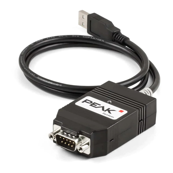
Appendix B Dimension Drawings Figure 15: View PCAN-USB FD. The figures do not show the actual size of the product. Appendix B Dimension Drawings PCAN-USB FD User Manual 1.5.0 © 2021 PEAK-System Technik GmbH... -
Page 33: Appendix C Quick Reference
Software/Hardware Installation under Windows Install the driver, before you connect the PCAN-USB FD adapter to the computer. You can download it from our website www.peak-system.com/quick/DL-Driver-E. After that, you connect the adapter to a USB port of the computer or of a connected USB hub. - Page 34 High-speed CAN connector (D-Sub, 9 pins) Appendix C Quick Reference PCAN-USB FD User Manual 1.5.0 © 2021 PEAK-System Technik GmbH...
Need help?
Do you have a question about the PCAN-USB FD and is the answer not in the manual?
Questions and answers