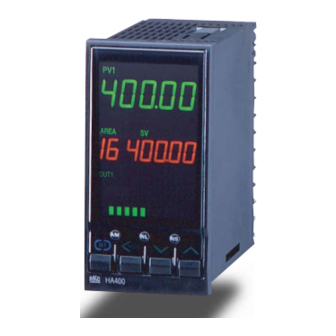
RKC INSTRUMENT HA400 Operation Manual
Digital controller
Hide thumbs
Also See for HA400:
- Communication instruction manual (210 pages) ,
- Instruction manual (170 pages) ,
- Connection manual (292 pages)

Related Manuals for RKC INSTRUMENT HA400


Summary of Contents for RKC INSTRUMENT HA400
- Page 1 Digital Controller HA400/HA900 HA401/HA901 Operation Manual IMR01N02-E2 RKC INSTRUMENT INC. ®...
- Page 2 Modbus is a registered trademark of Schneider Electric. DeviceNet is a registered trademark of Open DeviceNet Vender Association, Inc. Company names and product names used in this manual are the trademarks or registered trademarks of the respective companies. All Rights Reserved, Copyright 2002, RKC INSTRUMENT INC.
- Page 3 Thank you for purchasing this RKC instrument. In order to achieve maximum performance and ensure proper operation of your new instrument, carefully read all the instructions in this manual. Please place this manual in a convenient location for easy reference.
- Page 4 CAUTION This is a Class A instrument. In a domestic environment, this instrument may cause radio interference, in which case the user may be required to take adequate measures. This instrument is protected from electric shock by reinforced insulation. Provide reinforced insulation between the wire for the input signal and the wires for instrument power supply, source of power and loads.
- Page 5 When you do not have a necessary manual, please contact RKC sales office or the agent. Manual Manual Number Remarks HA400/HA900/HA401/HA901 IMR01N01-E A product box contains this manual. Instruction Manual This manual explains the mounting and wiring, a name of the front panel, and outline of the operation mode of the product.
- Page 6 SYMBOLS Safety Symbols : This mark indicates precautions that must be taken if there is danger of electric WARNING shock, fire, etc., which could result in loss of life or injury. : This mark indicates that if these precautions and operating procedures are not CAUTION taken, damage to the instrument may result.
-
Page 7: Table Of Contents
1.3 Model Code .....................2 1.4 Outline of Functions..................5 2. MOUNTING ................8 2.1 Mounting Environment..................8 2.2 Mounting Cautions...................8 2.3 Dimensions......................9 HA400/HA401......................9 HA900/HA901......................9 2.4 Procedures of Mounting and Removing ............10 Mounting procedures .....................10 Removing procedures....................10 3. WIRING ................11 3.1 Wiring Cautions .....................11 3.2 Terminal Layout.....................12... - Page 8 Page 5. SETTING ................22 5.1 Setting Procedure to Operation ..............22 5.2 Operation Menu.....................24 Input type and input range display .................25 5.3 Key Operation....................26 Scrolling through parameters ................. 26 Changing set value (SV) ..................26 Data Lock Function ....................27 How to restrict operation of the direct keys.............
- Page 9 Page 8. SETUP SETTING MODE ............ 40 8.1 Display Sequence..................40 8.2 Parameter List ....................41 8.3 Description of Each Parameter..............42 Heater break alarm 1 (HBA1) set value (HbA1) Heater break alarm 2 (HBA2) set value (HbA2) .............42 Heater break determination point 1 (HbL1) Heater break determination point 2 (HbL2) ............44 Heater melting determination point 1 (HbH1) Heater melting determination point 2 (HbH2) ............44...
- Page 10 Page 9.6 Input 1 (F21)/Input 2 (F22)................66 Input type selection (1. InP, 2. InP) ................66 Display unit selection (1. UnIT, 2. UnIT)..............67 Decimal point position (1. PGdP, 2. PGdP)............67 Input scale high (1. PGSH, 2. PGSH) ..............67 Input scale low (1. PGSL, 2. PGSL) ...............68 Input error determination point (high limit) (1.
- Page 11 Page 9.13 Control 1 (F51)/Control 2 (F52) ..............85 Control action type selection (1. oS, 2. oS) ............85 Integral/derivative time decimal point position (1.IddP, 2.IddP) ......85 Derivative gain (1. dGA, 2.dGA) ................85 ON/OFF action differential gap (upper) (1. oHH, 2. oHH) ........86 ON/OFF action differential gap (lower) (1.
- Page 12 Page 10.3 Monitoring Display in Operation..............102 10.4 Autotuning (AT) ..................105 Requirements for AT start..................105 AT cancellation ....................105 10.5 Auto/Manual Transfer ................106 Auto/Manual transfer by front key operation............106 Auto/Manual transfer by direct key (A/M) operation ..........107 Auto/Manual transfer by event input..............107 Procedure for setting the manipulated output value (MV) in Manual mode...107 10.6 Remote/Local Transfer ................108 Remote/Local transfer by front key operation............108...
- Page 13 Page APPENDIX A. Setting Data List.............. 124 A-1. SV Setting & Monitor Mode................124 A-2. Setup Setting Mode ...................126 A-3. Parameter Setting Mode ................129 A-4. Engineering Mode (F10 to F91) ..............131 B. Specifications..............150 C. Trans Dimensions for Power Feed Forward ....157 D.
- Page 14 MEMO i-12 IMR01N02-E2...
-
Page 15: Outline
Autotuning function corresponding to fast response • The HA400/HA900 is best suited for applications that reach setpoint quickly (within 30 seconds). * • The HA401/HA901 is best suited for applications that take more than 30 seconds to reach setpoint. * * Autotuning a process with a fast response may produce PID constants that would fluctuate the process excessively. -
Page 16: Model Code
Check whether the delivered product is as specified by referring to the following model code list. If the product is not identical to the specifications, please contact RKC sales office or the agent. High-speed AT type: HA400 HA400-□ -□ □-□... - Page 17 1. OUTLINE (3) Output 1 (OUT1) N : None T : Triac output 6 : Voltage output (1 to 5 V DC) M : Relay contact output 4 : Voltage output (0 to 5 V DC) 7 : Current output (0 to 20 mA DC) V : Voltage pulse output 5 : Voltage output (0 to 10 V DC) 8 : Current output (4 to 20 mA DC)
- Page 18 1. OUTLINE (9) CT input/Power feed forward input/Feedback resistance input (option) N : None S : CT 2 points (CTL-6-P-N) F : Feedback resistance input T : CT 1 point (CTL-12-S56-10L-N) P : CT 1 point (CTL-6-P-N) U : CT 2 points (CTL-12-S56-10L-N) 1 : Power feed forward input (one 100-120 V AC transformer included) 2 : Power feed forward input (one 200-240 V AC transformer included) 3 : CT 1 point (CTL-6-P-N) + Power feed forward input (one 100-120 V AC transformer included)
-
Page 19: Outline Of Functions
1. OUTLINE 1.4 Outline of Functions This section describes the input/output functions of the instrument. To learn how to set each function, see the respective page. INPUT In addition to measured input, 5 optional input functions are available. Measured input: 1-input or 2-input. - Page 20 1. OUTLINE Power feed forward (PFF) input: Power feed forward input is used for Power Feed Forward function to achieve accurate control. PFF monitors power supply voltage variation on a device and compensates control output from the controller. Two types of dedicated transformer is available. (Specify either of them when ordering) PFT-01 100 V type transformer (100 to 120 V AC) PFT-02...
- Page 21 1. OUTLINE Transmission output 1 to 3 (AO1 to AO3): Maximum three transmission output can be allocated to OUT1, OUT2, and OUT3. Maximum number of output available for transmission output varies by other output use for control output and event output. Parameter values shown in the following table can be output by transmission output.
-
Page 22: Mounting
2. MOUNTING This chapter describes installation environment, mounting cautions, dimensions and mounting procedures. WARNING To prevent electric shock or instrument failure, always turn off the power before mounting or removing the instrument. 2.1 Mounting Environment (1) This instrument is intended to be used under the following environmental conditions. (IEC61010-1) [OVERVOLTAGE CATEGORY II, POLLUTION DEGREE 2] (2) Avoid the following conditions when selecting the mounting location: •... -
Page 23: Dimensions
*4 When controllers are closely mounted, ambient temperature must not exceed 50 °C. For mounting of the HA400/HA401 or HA900/HA901, panel thickness must be between 1 to 10 mm. When mounting multiple HA400/HA401s or HA900/HA901s close together, the panel strength should be checked to ensure proper support. -
Page 24: Procedures Of Mounting And Removing
HA900/HA901 is used in the above figures for explanation, but Insert the L-shaped hook of screws, only turn one full the same mounting procedures also apply to HA400/HA401. the mounting bracket into the revolution after the screw groove, then firmly secure it in the groove. -
Page 25: Wiring
3. WIRING This chapter describes wiring cautions, wiring layout and wiring of terminals. WARNING To prevent electric shock or instrument failure, do not turn on the power until all the wiring is completed. 3.1 Wiring Cautions • For thermocouple input, use the appropriate compensation wire. •... -
Page 26: Terminal Layout
3. WIRING 3.2 Terminal Layout The terminal layout is as follows. HA400/HA401 is used in the figures for explanation, but the same terminal layouts also apply to HA900/HA901. 1-input controller Option Communication 2 Power supply voltage 100 to 240 V AC... -
Page 27: Wiring Of Each Terminal
Power consumption 90 to 264 V AC [Power supply voltage range], 50/60 Hz, HA400/HA401: 12 VA max. (at 100 V AC), 17 VA max. (at 240 V AC) (Rating 100 to 240 V AC) HA900/HA901: 13 VA max. (at 100 V AC), 19 VA max. (at 240 V AC) 21.6 to 26.4 V AC [Power supply voltage range],... -
Page 28: Output 1 To 3 (Out1 To Out3)
3. WIRING Output 1 to 3 (OUT1 to OUT3) • Terminal 11 and 12 are for output 1 (OUT1); Terminal 9 and 10 are for output 2 (OUT2); and Terminal 7 and 8 are for output 3 (OUT3). • Connect an appropriate load according to the output type. Relay contact output: Triac output: OUT1... -
Page 29: Measured Input
3. WIRING Measured input • For the 1-input controller, terminal 21 through 24 are allocated to the measured input. Thermocouple RTD input Voltage input Current input 3-wire system − − − 4-wire system • For the 2-input controller, terminal 22 through 24 are allocated to Input 1, and the terminal 19 through 21 are allocated to Input 2. -
Page 30: Remote Input (Option)
3. WIRING Remote input (option) • With non-isolated remote input option, terminal 19 to 20 are allocated to Remote Input. Any one of the following input types can be selected. Voltage (low): 0 to 100 mV DC, 0 to 10 mV DC, 0 to 1 V DC Voltage (high): 0 to 5 V DC, 1 to 5 V DC, 0 to 10 V DC −... -
Page 31: Ct Input/Power Feed Forward Input/Feedback Resistance Input (Option)
3. WIRING CT input/Power feed forward input/Feedback resistance input (option) • With CT input, Power Feed Forward input or feedback resistance input, terminal 16 through 18 are allocated to the specified input. • When using CT input, connect CTs to the relevant terminals. •... - Page 32 3. WIRING Connection Diagram Example [Connection to the RS-232C port of the host computer (master)] HA400/HA900 Host computer (master) (Slave) RS-232C SG (GND) SG (GND) SD (TXD) SD (TXD) RD (RXD) RD (RXD) RS (RTS) Shielded wire CS (CTS) Number of connection: 1 instrument...
-
Page 33: Parts Description
4. PARTS DESCRIPTION This chapter describes various display units and the key functions. HA400/HA401 PV1 PV2 MAN REM AT Upper display AREA PV2 Lower display Area display Output/Alarm lamp OUT1 OUT2 OUT3 OUT4 OUT5 ALM Bar gragh display Direct keys... - Page 34 4. PARTS DESCRIPTION Upper display Measured value 1 (PV1) lamp [Green] Lights when measured value 1 is displayed on the PV1/PV2 display unit. Measured value 2 (PV2) lamp * [Green] Lights when measured value 2 is displayed on the PV1/PV2 display unit. Manual (MAN) mode lamp [Green] Lights when operated in manual mode.
- Page 35 (Available with position proportioning PID control) [Example] * The number of dots: 10 dots (HA400/HA401) 20 dots (HA900/HA901) The bar-graph function is not activated at the factory unless the controller is specified as position proportioning PID controller when ordered Bar graph display can be selected in the Engineering Mode. See selecting the bar graph display (P.64).
-
Page 36: Setting
5. SETTING This chapter describes procedures to set operating conditions of a customer and parameter of various setting modes. 5.1 Setting Procedure to Operation Conduct necessary setting before operation according to the procedure described below. Mounting & Wiring When installing the instrument, Entry to data sheet see 2. - Page 37 5. SETTING Continued from the previous page. To use ramp/soak function Parameter data setting Set parameters to be related to operation in Parameter Setting Mode): • Setting event output/event input function • Setting of PID and control response relation, etc. Set the Setting change rate limiter, Area soak time and Link Up to 16 individual sets of parameters in Parameter...
-
Page 38: Operation Menu
5. SETTING 5.2 Operation Menu The controller has five different setting modes, and all settable parameters belongs to one of them. The following chart show how to access different setting mode. For the details of key operation, see 5.3 Key Operation (P. 26) This instrument returns to the PV1/SV1 monitor screen if no key Power ON operation is performed for more than 1 minute. -
Page 39: Input Type And Input Range Display
5. SETTING Input type and input range display This instrument immediately confirms inputs type symbol and input range following power ON. Example: When sensor type of Input 1 and Input 2 is K thermocouple (2-input controller) Power ON Symbol Unit for input and SV display (Celsius: °C, Fahrenheit: °F, Voltage/current input: no character shown) Input type symbol * Input 1... -
Page 40: Key Operation
5. SETTING 5.3 Key Operation Basic key operations common to each mode (set item change, set value change and registration) and Data Lock Function are described in the following. Scrolling through parameters • Press to scroll through parameters in the same mode/area. •... -
Page 41: Data Lock Function
5. SETTING Data Lock Function • The Data Lock Function limits access of unauthorized personnel to the parameters and prevents parameter change by mistake. • There are 8 set data lock levels. The set data lock level can be set in Setup Setting mode. Character display Parameters which can be changed Set value... -
Page 42: Changing Parameter Settings
5. OPERATION 5.4 Changing Parameter Settings Procedures to change parameter settings are shown below. Change Settings Example: Change the set value 1 (SV1) of Input 1 from 0.0 ° ° ° ° C to 200.0 ° ° ° ° C 1. - Page 43 5. OPERATION 3. Shift the high-lighted digit The high-lighted digit indicates which digit can be set. Press the shift key to high-light the hundreds digit. MODE MODE 4. Change the set value Press the UP key to change the numeral to 2. MODE MODE 5.
-
Page 44: Sv Setting & Monitor Mode
6. SV SETTING & MONITOR MODE 6.1 Display Sequence In SV Setting & Monitor mode, the following operations are possible. Change the set value (SV) Change Memory Area Monitor the measured value (PV) and the manipulated value (MV), etc. When the power is turned on, the controller goes to this mode after self-diagnostics. Use this mode during normal operation. -
Page 45: Procedure For Set Value (Sv) Setting
6. SV SETTING & MONITOR MODE 6.2 Procedure for Set Value (SV) Setting Up to 16 individual sets of SVs and parameters in Parameter Setting Mode can be stored and used in Multi-memory Area function. Some examples of changing the set value (SV) described in the following. The same setting procedure applies when parameters corresponding to the multi-memory area function are also set. -
Page 46: Parameter Setting Mode
7. PARAMETER SETTING MODE 7.1 Display Sequence In Parameter Setting mode, the following operations are possible. Set parameters relating to control such as PID constants, event set values, and the setting change rate limiter. To go to Parameter Setting mode, press and hold the SET key for 2 seconds at SV Setting &... - Page 47 7. PARAMETER SETTING MODE From Input 1_control response parameter setting screen SET key Input 2_proportional band Multi-memory area function: • Multi-Memory Area function can store up to 16 individual sets AREA of SVs and parameters in Parameter Setting mode. (P.37) One of the Areas is used for control, and the currently selected SET key area is “Control Area”.
-
Page 48: Parameter List
7. PARAMETER SETTING MODE 7.2 Parameter List Parameter Page Parameter Page Event 1 set value P. 35 Input 1_setting change P. 38 (EV1) rate limiter (up) (1.SVrU) Event 2 set value P. 35 Input 1_setting change P. 38 (EV2) rate limiter (down) (1.SVrd) Event 3 set value P. -
Page 49: Description Of Each Parameter
7. PARAMETER SETTING MODE 7.3 Description of Each Parameter Event 1 set value (EV1) Event 2 set value (EV2) Event 3 set value (EV3) Event 4 set value (EV4) EV1 through EV4 are set values of the event action. Deviation: −Input span to +Input span Data range: Process: Input scale low to Input scale high... -
Page 50: Lba Deadband (Lbd1, Lbd2)
7. PARAMETER SETTING MODE LBA deadband (Lbd1, Lbd2) The LBA deadband gives a neutral zone to prevent the control loop break alarm (LBA) from malfunctioning caused by disturbance. Data range: 0.0 to Input span Factory set value: 0.0 LBA Deadband function: The LBA may malfunction due to external disturbance from outside even when the control does not have any problem. -
Page 51: Proportional Band (1. P, 2. P) For Pi/Pid Control
7. PARAMETER SETTING MODE Proportional band (1. P, 2. P) for PI/PID control Data range: TC/RTD input: 0 to Input span Voltage/current input: 0.0 to 1000.0 % of input span 0 (0.0): ON/OFF action Factory set value: 30.0 Related parameters: ON/OFF action differential gap (upper/lower) (P. 86) Integral time (1. -
Page 52: Setting Change Rate Limiter (Up) (1.Svru, 2.Svru)
7. PARAMETER SETTING MODE Setting change rate limiter (up) (1.SVrU, 2.SVrU) This function is to allow the set value (SV) to be automatically changed at specific rates when a new set value (SV). SVrU is used when the SV is changed to a higher SV. Data range: OFF (Unused), 0.1 to Input span/unit time Factory set value: OFF... -
Page 53: Area Soak Time (Ast)
7. PARAMETER SETTING MODE Area soak time (AST) Area Soak Time is used for ramp/soak control function in conjunction with Link Area Number and Setting Change Rate Limiter (up/down). Data range: 0 hour 00.00 second to 9 minutes 59.99 seconds or 0 hour 00 minute 00 second to 9 hours 59 minutes 59 seconds Factory set value: 0.00.00 (0 minute 00.00 second) The unit time can be changed by the Soak Time Unit Selection in the Engineering mode. -
Page 54: Setup Setting Mode
8. SETUP SETTING MODE 8.1 Display Sequence In Setup Setting mode, the following operations are possible. Change other operation/control related parameters Change Communication parameters Change Data Lock Level To go to Setup Setting mode from SV Setting & Monitor mode, press the shift key while pressing the SET key. SV setting &... -
Page 55: Parameter List
8. SETUP SETTING MODE 8.2 Parameter List Parameter Page Parameter Page Heater break alarm 1 P. 42 Device address 1 P. 46 (HBA1) set value (HbA1) (Slave address 1) (Add1) Heater break P. 44 Communication speed 1 P. 46 determination point 1 (HbL1) (bPS1) Heater melting... -
Page 56: Description Of Each Parameter
8. SETUP SETTING MODE 8.3 Description of Each Parameter Heater break alarm 1 (HBA1) set value (HbA1) Heater break alarm 2 (HBA2) set value (HbA2) The HBA set value used for the heater break alarm function is set. Two types of heater break alarms are available: Heater break alarm (HBA) type A and heater break alarm (HBA) type B. - Page 57 8. SETUP SETTING MODE Continued from the previous page. < Heater break alarm (HBA) type B > Heater Break Alarm (HBA) type B can correspond to the time proportioning and continuous outputs. For heater break alarm (HBA) type B, the current value at each control output value is computed assuming that the heater current value (squared) is proportional* to the control output value with the heater break set value set to a reference.
-
Page 58: Heater Break Determination Point 1 (Hbl1) Heater Break Determination Point 2 (Hbl2)
PV digital filter (1. dF, 2. dF) This item is the time of the first-order lag filter eliminate noise against the measured input. Data range: OFF (Not provided), 0.01 to 10.00 seconds Factory set value: HA400/HA900: OFF HA401/HA901: 1.00 IMR01N02-E2... -
Page 59: Pv Ratio (1. Pr, 2. Pr)
8. SETUP SETTING MODE PV ratio (1. Pr, 2. Pr) PV ratio is a multiplier to be applied to the measured value (PV). The PV bias is used to compensate the individual variations of the sensors or correct the difference between the measured value (PV) of other instruments. -
Page 60: Device Address 1 (Slave Address 1) (Add1)
19.2: 19200 bps 38.4: 38400 bps Factory set value: 9.6 Set the same communication speed for both the HA400/HA900/HA401/HA901 (slave) and the host computer (master). Data bit configuration 1 (bIT1) This item is data bit configuration of communication 1 function (optional). -
Page 61: Interval Time 1 (Int1)
If the interval time between the two is too short, the HA400/HA900 (HA401/HA901) may send data before the host computer is ready to receive it. In this case, communication transmission cannot be conducted correctly. -
Page 62: Data Bit Configuration 2 (Bit2)
Interval Time function: See “Interval time 1 (InT1)” on page 47. If the interval time between the two is too short, the HA400/HA900 (HA401/HA901) may send data before the host computer is ready to receive it. In this case, communication transmission cannot be conducted correctly. -
Page 63: Set Lock Level (Lck)
8. SETUP SETTING MODE Set lock level (LCK) The set lock level restricts parameter setting changes by key operation (Set data lock function). This function prevents the operator from making errors during operation. Data range: (1) Parameters other than set value (SV) and event set value (EV1 to EV4): 0: Unlock 1: Lock (2) Event set value (EV1 to EV4) -
Page 64: Engineering Mode
9. ENGINEERING MODE CAUTION Parameters in the Engineering mode should be set according to the application before setting any parameter related to operation. Once the Parameters in the Engineering mode are set correctly, those parameters are not necessary to be changed for the same application under normal conditions. - Page 65 9. ENGINEERING MODE (Input 2) UP or DOWN Event input (Event input) logic selection SET key SET key (P. 70) UP or DOWN Output logic Output 1 timer Output 2 timer Output 3 timer Output 4 timer Output 5 timer (Output) selection setting...
- Page 66 9. ENGINEERING MODE (CT1) UP or DOWN Number of heater break alarm 2 (HBA2) delay Heater break alarm 2 (CT2) times CT2 ratio (HBA2) type selection CT2 assignment SET key SET key SET key SET key SET key (P. 80) UP or DOWN Hot/Cold start Input 2_...
- Page 67 9. ENGINEERING MODE (AT2) UP or DOWN Action at feedback Feedback resistance Open/Close output Open/Close output Feedback adjustment (FBR) input resistance (FBR) input neutral zone differential gap preparation screen (Position proportioning PID action) asignment error SET key SET key SET key SET key SET key SET key...
-
Page 68: Parameter List
9. ENGINEERING MODE 9.2 Parameter List Function block Parameter Page Screen STOP display selection P. 63 (SPCH) (F10.) configuration Bar graph display selection P. 64 (dE) Bar graph resolution setting (dEUT) Direct key Auto/Manual transfer key operation selection P. 65 (Fn1) (F11.) Remote/Local transfer key operation selection... - Page 69 9. ENGINEERING MODE Continued from the previous page. Function block Parameter Page Transmission Transmission output 2 type selection P. 74 (Ao2) (F32.) output 2 Transmission output 2 scale high (AHS2) Transmission output 2 scale low (ALS2) Transmission Transmission output 3 type selection P.
- Page 70 9. ENGINEERING MODE Continued from the previous page. Function block Parameter Page Control Hot/Cold start selection P. 82 (Pd) (F50.) Input 2_use selection (CAM) Cascade ratio (CAr) Cascade bias P. 83 (CAb) SV tracking P. 84 (TrK) Control 1 Input 1_control action type selection P.
- Page 71 9. ENGINEERING MODE Continued from the previous page. Function block Parameter Page Autotuning 2 Input 2_AT bias P. 91 (2. ATb) (F54.) (AT2) Input 2_AT cycle P. 92 (2. ATC) Input 2_AT differential gap time P. 93 (2. ATH) Position Open/Close output neutral zone P.
-
Page 72: Precaution Against Parameter Change
9. ENGINEERING MODE 9.3 Precaution Against Parameter Change If any of the following parameters is changed, the set values of relevant parameters are initialized or is automatically converted according to the new setting. It may result in malfunction or failure of the instrument. - Input Type Selection of Input 1 (1.InP) - Input Type Selection of Input 2 (2. - Page 73 9. ENGINEERING MODE Continued from the previous page. Default value Mode Description Voltage/current TC input RTD input input Transmission output 1 scale low Measured value (PV) and set value (SV): Input scale low Manipulated output value (MV): 0.0 Transmission output 2 scale low Engineering Deviation: −Input span mode...
- Page 74 9. ENGINEERING MODE When any one of the following parameters’ settings are changed, - Event 1 Type Selection (ES1) - Event 2 Type Selection (ES2) - Event 3 Type Selection (ES3) - Event 4 Type Selection (ES4) all parameter settings shown in the table below will be changed to Factory Default Values according to the new setting.
- Page 75 9. ENGINEERING MODE When any one of the following parameters’ settings are changed, - Input 1_Decimal Point Position (1.PGdP) - Input 2_Decimal Point Position (2.PGdP) all parameter settings shown in the table below will be automatically converted into the a values to match the new decimal point position as long as the converted values are in the acceptable range of each parameter.
- Page 76 9. ENGINEERING MODE Continued from the previous page. Precaution and Example of automatic conversion • Decimal point position moves in accordance with the setting change. Example: When the setting of the decimal point position is changed from 0 (no decimal place) to 1 (the first decimal place) with Input scale high (1.PGSH) set to 800 °C: (1.PGSH) (1.PGSH)
-
Page 77: Screen Configuration (F10)
9. ENGINEERING MODE 9.4 Screen Configuration (F10) STOP display selection (SPCH) STOP message for control STOP mode can be displayed either on the upper display or the lower display. SPCH is to select the display to show the STOP message. Data range: 0: Displays on the measured value (PV1/PV2) unit (TYPE 1) 1: Displays on the set value (SV) unit (TYPE 2) -
Page 78: Bar Graph Display Selection (De)
Displays the feedback resistance input value (POS). It is available only with position value (POS) display proportioning PID control. [Display example] * The number of dot points: 10 dots (HA400/HA401) 20 dots (HA900/HA901) Bar graph resolution setting (dEUT) Use to set the bar graph display resolution for the deviation display. -
Page 79: Direct Key (F11)
9. ENGINEERING MODE 9.5 Direct Key (F11) (Fn1) Auto/Manual transfer key operation selection Use to select Use/Unuse of Auto/Manual transfer key (A/M). Data range: 0: Unused 1: Auto/Manual transfer for input 1 2: Auto/Manual transfer for input 2 3: Common Auto/Manual transfer for input 1 and input 2 Factory set value: 3 Remote/Local transfer key operation selection (Fn2) Use to select Use/Unuse of Remote/Local transfer key (R/L). -
Page 80: Input 1 (F21)/Input 2 (F22)
9. ENGINEERING MODE 9.6 Input 1 (F21) Input 2 (F22) Input type selection (1. InP, 2. InP) Data range: 0 to 23 (see the following table) [Input Range Table] Set value Input type Input range Hardware −200 to +1372 °C or −328.0 to +2501.6 °F −200 to +1200 °C or −328.0 to +2192.0 °F −50 to +1768 °C or −58.0 to +3214.4 °F −50 to +1768 °C or −58.0 to +3214.4 °F... -
Page 81: Display Unit Selection (1. Unit, 2. Unit)
9. ENGINEERING MODE Display unit selection (1. UnIT, 2. UnIT) Use to select the temperature unit for thermocouple (TC) and RTD inputs. 0: °C Data range: 1: °F Factory set value: 0 Decimal point position (1. PGdP, 2. PGdP) Use to select the decimal point position of the input range. Data range: Thermocouple (TC) inputs: 0 to 1... -
Page 82: Input Scale Low (1. Pgsl
9. ENGINEERING MODE Input scale low (1. PGSL, 2. PGSL) This value is to set the low limit of the input scale range. Data range: Thermocouple (TC)/RTD inputs: Minimum value of the selected input range to Input scale high Voltage (V)/current (I) inputs: −19999 to +99999 (Varies with the setting of the decimal point position) Factory set value: Thermocouple (TC)/RTD inputs: Minimum value of the selected input range... -
Page 83: Burnout Direction (1. Bos, 2. Bos)
9. ENGINEERING MODE Burnout direction (1. boS, 2. boS) Use to select Burnout Direction in input break. When input break is detected by the controller, the measured value go either Upscale or Downscale according to the Burnout Direction setting. Data range: 0: Upscale 1: Downscale Factory set value: 0... -
Page 84: Event Input (F23)
9. ENGINEERING MODE 9.7 Event Input (F23) Event input logic selection (dISL) Use to assign the function (memory area, operation mode) for the event inputs (DI 1 to DI 7). Data range: 0 to 6 (see the following table) [Function Assignment Table] DI 1 DI 2 DI 3... - Page 85 9. ENGINEERING MODE Continued from the previous page. DI Status for mode transfer No event input or Contact closed Contact open not selected RUN/STOP transfer RUN (Control RUN) STOP (Control STOP) RUN (Control RUN) Auto/Manual transfer Auto Manual Auto Remote or cascade control Local Local Remote/Local transfer...
-
Page 86: Output (F30)
9. ENGINEERING MODE 9.8 Output (F30) Output logic selection (LoGC) This is used to assign the output function (control output, event, etc.) for the output (OUT1 to OUT5). Data range: 1 to 11 (see the following table) [Output Assignment Table] (M: Relay contact output, V: Voltage pulse output, T: Triac output, R: Current output, E: Voltage) OUT1 OUT2... -
Page 87: Output Timer Setting (Ott1 To Ott5)
9. ENGINEERING MODE Output timer setting (oTT1 to oTT5) Output Timer Setting is to set an output delay time for event outputs. Data range: 0.0 to 600.0 seconds Factory set value: Related parameters: Output logic selection (P. 72), Event type selection (P. 75) Output Timer Setting function: When an event condition becomes On status, the output is suppressed until the Output Timer set time elapses. -
Page 88: Transmission Output 3 (F33)
9. ENGINEERING MODE 9.9 Transmission Output 1_Type (F31) Transmission Output 2_Type (F32) Transmission Output 3_Type (F33) Transmission output type selection (Ao1, Ao2, Ao3) Use to select the transmission output type. Data range: - - - - -: None 2. PV: Input 2_ measured value (PV) 1. -
Page 89: Event 1 (F41)/Event 2 (F42)/Event 3 (F43)/Event 4 (F44)
9. ENGINEERING MODE 9.10 Event 1 Type (F41) Event 3 Type (F43) Event 2 Type (F42) Event 4 Type (F44) Event type selection (ES1, ES2, ES3, ES4) Use to select a type of the event 1, 2, 3 and 4. Data range: 0: None 5: Process high... - Page 90 9. ENGINEERING MODE Continued from the previous page. Control loop break alarm (LBA) The control loop break alarm (LBA) function is used to detect a load (heater) break or a failure in the external actuator (magnet relay, etc.), or a failure in the control loop caused by an input (sensor) break. The LBA function is activated when control output reaches 0 % (low limit with output limit function) or 100 % (high limit with output limit function).
-
Page 91: Event Hold Action (Eho1, Eho2, Eho3, Eho4)
9. ENGINEERING MODE Event hold action (EHo1, EHo2, EHo3, EHo4) Use to set a event hold action for the Event 1, 2, 3 or 4. Data range: 0: OFF 1: ON 2: Re-hold action ON Factory set value: Related parameters: Event type selection (P. -
Page 92: Event Differential Gap (Eh1, Eh2, Eh3, Eh4)
9. ENGINEERING MODE (EH1, EH2, EH3, EH4) Event differential gap Use to set a differential gap of the event 1, 2, 3 or 4. Data range: 0 to Input span Thermocouple (TC) /RTD inputs: 2.0 °C [°F] Factory set value: 0.2 % of input span Voltage (V) /current (I) inputs: Related parameters: Event type selection (P. -
Page 93: Action At Event Input Error (Eeo1, Eeo2, Eeo3, Eeo4)
9. ENGINEERING MODE Event action at input error (EEo1, EEo2, EEo3, EEo4) Event action at input error is to select the event action when the measured value reaches the input error determination point (high or low limit). Data range: 0: Normal processing 1: Turn the event output ON Factory set value: Related parameters: Input error determination point high limit (P. -
Page 94: Current Transformer (Ct1) Input (F45)
9. ENGINEERING MODE 9.11 Current Transformer Input 1 (CT1) (F45) Current Transformer Input 2 (CT2) (F46) The settings of parameters in this group become valid on the controller with the CT input (optional) function. CT ratio (CTr1, CTr2) Use to set the number of turns (ratio) of the current transformer that is used with the heater break alarm (HBA). Data range: 0 to 9999 Factory set value:... -
Page 95: Number Of Heater Break Alarm (Hba) Delay Times (Hbc1, Hbc2)
9. ENGINEERING MODE Number of heater break alarm (HBA) delay times (HbC1, HbC2) It the number of heater break alarm (HBA) times continues its preset times (the number of sampling times), the heater break alarm is turned on. Data range: 0 to 255 Factory set value: Related parameters: Output logic selection (P. -
Page 96: Control (F50)
9. ENGINEERING MODE 9.12 Control (F50) Hot/Cold start selection (Pd) Use to select the start mode at power recovery. Data range: See the following table Power failure less than 3 seconds Power failure more than 3 seconds value Hot start 1 Hot start 1 Hot start 1 Hot start 2... -
Page 97: Cascade Bias (Cab)
9. ENGINEERING MODE Cascade bias (CAb) The cascade bias is applied to the input value on the slave side in the cascade control. −Input span to +Input span Data range: Factory set value: 0 Related parameters: Cascade ratio (P. 82) The functional description of the cascade control is shown in the following. -
Page 98: Sv Tracking (Trk)
9. ENGINEERING MODE SV tracking (TrK) To select Use/Unuse of SV tracking. Data range: 0: Unused 1: Used Factory set value: 1 SV Tracking function: With SV Tracking function, when Remote/Local mode is transferred from Remote to Local, the set value used in Remote mode before the mode transfer will be kept using in Local mode to prevent rapid set value change. -
Page 99: Control 1 (F51)/Control 2 (F52)
9. ENGINEERING MODE 9.13 Control 1 (F51) Control 2 (F52) Control action type selection (1. oS, 2. oS) Use to select direct action/reverse action. Data range: 0: Direct action 1: Reverse action Factory set value: 1 Control action type: Direct action: The manipulated output value (MV) increases as the measured value (PV) increases. -
Page 100: On/Off Action Differential Gap (Upper) (1. Ohh, 2. Ohh)
9. ENGINEERING MODE ON/OFF action differential gap (upper) (1. oHH, 2. oHH) Use to set the ON/OFF control differential gap (upper). Data range: 0 to Input span Thermocouple (TC)/RTD inputs: 1.0 °C [°F] Factory set value: 0.1 % of Input span Voltage (V)/current (I) inputs: Related parameters: ON/OFF action differential gap (lower) (P. -
Page 101: Action At Input Error (High Limit) (1.Aove, 2.Aove)
9. ENGINEERING MODE Action at input error (high limit) (1.AoVE, 2.AoVE) Use to select the action when the measured value reaches the input error determination point (high limit). Data range: 0: Normal control 1: Output Manipulated Output Value at Input Error (PSM) Factory set value: Related parameters: Input error determination point (high limit) (P. -
Page 102: Output Change Rate Limiter (Up) (1. Oru, 2. Oru)
9. ENGINEERING MODE Output change rate limiter (up) (1. orU, 2. orU) Use to set the output change rate limiter (upward side) to limit of the variation of output is set. 0.0 to 1000.0 %/second (0.0: OFF) Data range: Factory set value: Related parameters: Output change rate limiter down (P. -
Page 103: Output Change Rate Limit (Down) (1. Ord, 2. Ord)
9. ENGINEERING MODE Output change rate limiter (down) (1. ord, 2. ord) Use to set the output change rate limiter (down). 0.0 to 1000.0 %/second (0.0: OFF) Data range: Factory set value: Related parameters: Output change rate limiter (up) (P. 88), Output limiter (high limit) (P. 89), Output limiter (low limit) (P. -
Page 104: Power Feed Forward (1. Pff, 2. Pff)
The power feed forward function monitors the electrical load through a dedicated transformer, and adjusts manipulated output to compensate power supply fluctuation. If the function detects approximately 30 % voltage drop, the controller automatically stops PID control. HA400/HA900 HA401/HA901 Sensor input Power feed input... -
Page 105: Power Feed Forward Gain (1. Pffs, 2. Pffs)
9. ENGINEERING MODE Power feed forward gain (1. PFFS, 2. PFFS) Use to set a gain used for the power feed forward (PFF) function. Power Feed Forward gain should not be changed under ordinary operation. Data range: 0.01 to 5.00 Factory set value: 1.00 Related parameters: Power feed forward selection (P. -
Page 106: At Cycle (1. Atc, 2. Atc)
9. ENGINEERING MODE AT cycle (1. ATC, 2. ATC) Use to select the number of ON/OFF cycles used to calculate PID values during autotuning. Data range: 0: 1.5 cycles 1: 2.0 cycles 2: 2.5 cycles 3: 3.0 cycles Factory set value: Related parameters: PID/AT transfer (P. -
Page 107: At Differential Gap Time (1. Ath, 2. Ath)
Data range: 0.00 to 50.00 seconds Factory set value: HA400/HA900: 0.10 HA401/HA901: 10.00 Related parameters: PID/AT transfer (P. 101), Autotuning (P. 105) Functional description: In order to prevent the output from chattering due to the fluctuation of a measured value (PV) caused by noise during autotuning, the output on or off state is held until “AT... -
Page 108: Position Proportioning Pid Action (F55)
9. ENGINEERING MODE 9.15 Position Proportioning PID Action (F55) The settings of parameters in this group become valid on the controller with the feedback resistance input (optional). Open/Close output neutral zone (Ydb) Use to set Open/Close output neutral zone. 0.1 to 10.0 % of output Data range: Factory set value: 10.0... -
Page 109: Open/Close Output Differential Gap (Yhs)
9. ENGINEERING MODE Open/Close output differential gap (YHS) Use to set differential gap of Open/Close output used in the position proportioning PID control. 0.1 to 5.0 % Data range: Factory set value: Related parameters: Open/Close output neutral zone (P. 94), Action at feedback resistance (FBR) input error (P. -
Page 110: Feedback Adjustment Preparation Screen (Pos)
The position proportioning PID control is performed by feeding back both the valve opening (feedback resistance input) from the control motor and measured value (PV) from the controlled object in the flow control. [Wiring Example] HA400 Power supply to control motor •... -
Page 111: Communication Function (F60)
9. ENGINEERING MODE 9.16 Communication Function (F60) Communication protocol selection (CMPS1, CMPS2) Use to select the protocol of communication 1 and 2. Data range: 0: RKC communication 1: Modbus Factory set value: Communication 1: 0 (RKC communication) Communication 2: 0 (RKC communication) Related parameters: Communication 1: Device address 1 (P. -
Page 112: Set Value 1 (Sv1) (F71)/Set Value 2 (Sv2) (F72)
9. ENGINEERING MODE 9.18 Set Value 1 (SV1) (F71) Set Value 2 (SV2) (F72) Setting limiter (high limit) (1. SLH, 2. SLH) Use to set a high limit of the set value. Data range: Setting limiter (low limit) to Input scale high Factory set value: Input 1_setting limiter (high limit) [1.SLH]: Input 1_input scale high Input 2_setting limiter (high limit) [2.SLH]: Input 2_input scale high... -
Page 113: System Information Display (F91)
9. ENGINEERING MODE 9.19 System Information Display (F91) System information (see below) can be checked on function block F91. Upper display: Character of the parameter Lower display: value Function block F91 Press the SET key ROM version display (RoM) Displays the version of loaded software. Press the SET key Integrated operating time display (WT) Displays the integrated total operating time of the controller. -
Page 114: Operation
10. OPERATION 10.1 Control RUN and STOP There is no power switch on this instrument, and the instrument starts operation immediately following initial power-ON (Factory set value: RUN). There are parameters in Engineering Mode which can not be changed when the controller is in RUN mode. Press the direct key (R/S) to change the RUN/STOP mode from RUN to STOP when a change for the parameters in Engineering Mode is necessary. -
Page 115: Configuration Of Operation Mode
10. OPERATION 10.2 Configuration of Operation Mode Display Sequence The operation mode is used to selects the operation modes (PID/AT, Auto/Manual, Remote/Local, RUN/STOP) of the instrument. Every time the SET key or the shift key is pressed, the display goes to the next parameters. SV Setting &... -
Page 116: Monitoring Display In Operation
10. OPERATION 10.3 Monitoring Display in Operation In SV Setting & Monitor mode, the following operations are possible. Change the set value (SV) Change Memory Area Monitor the measured value (PV) and the manipulated value (MV), etc. Use this mode during normal operation. Display Sequence Input 1_measured value (PV1)/set value (SV1) monitor Measured value 1 (PV1) - Page 117 10. OPERATION Continued from the previous page. SET key Remote input value monitor Displays the remote set value which is the control target value in the Remote (REM) mode. Displayed only when the remote input function is provided. Display range: Input 1_setting limiter (low limit) to Input 1_setting limiter (high limit) OUT1 SET key Cascade monitor...
- Page 118 10. OPERATION Continued from the previous page. SET key Current transformer input value 1 (CT1) monitor Displays the input value of the current transformer 1 (CT1) used when the instrument is provided with the heater break alarm 1 function. Display range: 0.0 to 30.0 A or 0.0 to 100.0 A The CT input cannot measure less than 0.4 A.
-
Page 119: Autotuning (At)
10. OPERATION 10.4 Autotuning (AT) Autotuning (AT) automatically measures, calculates and sets the optimum PID constants. The followings are the conditions necessary to carry out autotuning and the conditions which will cause the autotuning to stop. Requirements for AT start Start the autotuning when all following conditions are satisfied: To start autotuning, go to PID/AT transfer in Operation mode. -
Page 120: Auto/Manual Transfer
10. OPERATION 10.5 Auto/Manual Transfer The Auto/Manual transfer can be made by event input (option) or communication (option) other than the key operation. For details of Auto/Manual transfer by communication, see the Communication Instruction Manual (IMR01N03-E ).* * See Communication Instruction Manual (IMR01N04-E ) for PROFIBUS and Communication Instruction Manual (IMR01N05-E ) for DeviceNet. -
Page 121: Auto/Manual Transfer By Direct Key (A/M) Operation
10. OPERATION Auto/Manual transfer by direct key (A/M) operation Every time the UP key or the DOWN key is pressed, the Auto mode is changed to the Manual mode alternately. AREA MAN REM AT AREA MAN REM AT Displays Input number (1 or 2) only when either Input 1 or Input 2 is OUT1... -
Page 122: Remote/Local Transfer
10. OPERATION 10.6 Remote/Local Transfer The Remote/Local transfer can be made by event input (option) or communication (option) other than the key operation. For details of the Remote/Local transfer by communication, see the Communication Instruction Manual (IMR01N03-E ).* * See Communication Instruction Manual (IMR01N04-E ) for PROFIBUS and Communication Instruction Manual (IMR01N05-E ) for DeviceNet. -
Page 123: Remote/Local Transfer By Event Input
10. OPERATION Remote/Local transfer by event input Remote/Local transfer by the event input is possible with the event input logic selection (P. 70) of the engineering mode. The table below shows the actual operation modes and lamp status under different combinations of settings by front key, communication and event input. -
Page 124: Run/Stop Transfer By Direct Key (R/S) Operation
10. OPERATION RUN/STOP transfer by direct key (R/S) operation Every time the RUN/STOP (R/S) transfer key is pressed, the RUN mode is changed to the STOP mode alternately. AREA MAN REM AT AREA MAN REM AT MODE MODE RUN mode STOP mode The controller status at STOP mode is the same as that of Power-off. -
Page 125: Control Area Transfer
10. OPERATION 10.8 Control Area Transfer The control area transfer can be made by event input (option) or communication (option) other than the key operation. For details of transfer by communication, see the Communication Instruction Manual (IMR01N03-E ).* * See Communication Instruction Manual (IMR01N04-E ) for PROFIBUS and Communication Instruction Manual (IMR01N05-E ) for DeviceNet. -
Page 126: Start Operation When Power Failure Recovers
10. OPERATION 10.9 Start Operation when Power Failure Recovers The operation of this instrument is not affected by a power failure of 20 ms or less. The control start mode at power recovery after more than 20 ms power failure can be selected as follows. Power failure Power failure less than 3 seconds... -
Page 127: Ramp/Soak Control
10. OPERATION 10.10 Ramp/Soak Control Ramp/Soak control is possible by using Area Soak Time, Link Area Number and Setting Change Rate Limiter (up/down) in Parameter Setting mode (P. 32). The operating procedure is described in the following. Example: Ramp/Soak control by linking Memory area 1 to 3 The following is based on assumptions described below. - Page 128 10. OPERATION 9. Press the SET key to store the new value. The display goes 16. Press the SET key until Area soak time setting screen is to the next parameter. displayed. AREA AREA Flashing Factory set value: 0.00.00 (0 min. 00.00 sec.) (Example: Even 1set value setting screen) 10.
- Page 129 10. OPERATION 23. Press the UP key to change the numeral to 3. Check that STEP 2: this screen is set to OFF. Set the SV to each of Memory area 1, 2 and 3. 1. Press the SET key for 2 seconds to change the mode from the Parameter Setting mode to SV Setting &...
- Page 130 10. OPERATION 7. Press the shift key until the memory area display unit is 14. Press the UP key to change the numeral to 3. The number displayed. in AREA (Area number) display flashes. AREA Memory area No. 3 AREA High-light 8.
-
Page 131: Error Displays
11. ERROR DISPLAYS 11.1 Overscale and Underscale The table below shows displays, description, control actions and solutions when the measured value (PV) exceeds the display range. Display Description Action (Output) Solution Check input type, input Measured Input error Action at input error: range, sensor and sensor value (PV) Measured... -
Page 132: Self-Diagnostic Error
11. ERROR DISPLAYS 11.2 Self-diagnostic Error Displays and description of self-diagnostics are described in the following table: Upper Lower Description Action Solution display display Display: Error display Adjusted data error Turn off the power Output: once. If an error occurs •... -
Page 133: Troubleshooting
12. TROUBLESHOOTING This section explains probable causes and treatment procedures if any abnormality occurs in the instrument. For any inquiries, please contact RKC sales office or the agent, to confirm the specifications of the product. If it is necessary to replace a device, always strictly observe the warnings below. WARNING To prevent electric shock or instrument failure, always turn off the system power before replacing the instrument. -
Page 134: Control
12. TROUBLESHOOTING Continued from the previous page. Problem Probable cause Solution Display is abnormal Remote setting signal is input in Insert an isolator to enable isolated parallel to two or more this remote setting signal input for each instruments which use grounding instrument. -
Page 135: Operation
12. TROUBLESHOOTING Continued from the previous page. Problem Probable cause Solution Autotuning (AT) function not Requirements for performing the Satisfy the requirements for activated autotuning (AT) function are not performing the autotuning (AT) satisfied function by referring to 10.4 Autotuning (P. 105). Autotuning (AT) suspended Requirements for suspending the Identify causes for autotuning (AT) -
Page 136: Other
12. TROUBLESHOOTING Continued from the previous page. Problem Probable cause Solution Set value (SV) does not become The setting limiter is set Change the setting limiter setting more than (or less than) a specific by referring to 9.18 Set Value 1 value (SV1)/Set Value 2 (SV2) (P. -
Page 137: Removing The Internal Assembly
13. REMOVING THE INTERNAL ASSEMBLY Usually, this instrument is not necessary to remove the internal assembly from the case. When removing the internal assembly without disconnecting the external wiring, take the following steps. WARNING To prevent electric shock or instrument failure, only qualified personnel should be allowed to pull out the internal assembly. -
Page 138: Appendix A. Setting Data List
APPENDIX A. Setting Data List A-1. SV Setting & Monitor Mode Factory set User set Name Parameter Data range Page value value Input 1_ The upper section: P. 30 measured value (PV1)/ Displays input 1_PV1 P. 102 set value (SV1) monitor The lower section: Displays input 1_SV1 ... - Page 139 APPENDIX Continued from the previous page. Factory set User set Name Parameter Data range Page value value Memory area selection 1 to 16 P. 30 P. 104 (ArE) Memory area soak time 0 minute 00.00 second to P. 30 monitor 9 minutes 59.99 seconds or P.
-
Page 140: A-2. Setup Setting Mode
0.0: Heater melting determination is invalid −Input span to +Input span Input 1_PV bias P. 44 (1. Pb) Input 1_PV digital filter OFF (Not provided) HA400/HA900: P. 44 0.01 to 10.00 seconds (1. dF) HA401/HA901: 1.00 Input 1_PV ratio 0.500 to 1.500 1.000... - Page 141 APPENDIX Continued from the previous page. Factory set User set Name Parameter Data range Page value value 0.00 to 25.00 % of input span Input 2_PV low input cut-off 0.00 P. 45 (2. PLC) Input 2_proportional cycle 0.1 to 100.0 seconds Relay contact P.
- Page 142 APPENDIX Data bit configuration Set value Data bit Parity bit Stop bit (8n1) None (8n2) None (8E1) (8E2) Even (8o1) (8o2) Even (7n1) None (7n2) None (7E1) (7E2) (7o1) Even (7o2) Even (7n1 to 7o2: Invalid for Modbus) Set lock level list Set value Parameters which can be changed 00000...
-
Page 143: A-3. Parameter Setting Mode
APPENDIX A-3. Parameter Setting Mode Factory set User set Name Parameter Data range Page value value Event 1 set value Deviation: 50.0 P. 35 −Input span to +Input span (EV1) Process/SV: Input scale low to Input scale high Event 2 set value Deviation: 50.0 P. - Page 144 APPENDIX Continued from the previous page. Factory set User set Name Parameter Data range Page value value Input 1_control response 0: Slow P. 37 parameter 1: Medium (1. Rpt) 2: Fast Input 2_proportional band TC/RTD input: 30.0 P. 37 0 to Input span (2.
-
Page 145: A-4. Engineering Mode (F10 To F91)
APPENDIX A-4. Engineering Mode Function block F10: Screen configuration Factory set User set Name Parameter Data range Page value value STOP display selection 0: Displays on the measured value P. 63 (PV1/PV2) unit (SPCH) 1: Displays on the set value (SV) unit Bar graph display selection 0: No display... - Page 146 APPENDIX Function block F21: Input 1 Factory set User set Name Parameter Data range Page value value Input 1_input type selection TC input Depend on P. 66 model code. −200 to +1372 °C (1. InP) −328.0 to 2501.6 °F When not −200 to +1200 °C specifying: −328.0 to 2192.0 °F...
- Page 147 APPENDIX Continued from the previous page. Factory set User set Name Parameter Data range Page value value Input 1_decimal point 0: No decimal place P. 67 position 1: One decimal place (1.PGdP) 2: Two decimal places 3: Three decimal places 4: Four decimal places Input 1_input scale high TC/RTD input:...
- Page 148 APPENDIX Function block F22: Input 2 Factory set User set Name Parameter Data range Page value value Input 2_input type selection TC input Depend on P. 66 model code. −200 to +1372 °C (2. InP) −328.0 to 2501.6 °F When not −200 to +1200 °C specifying: −328.0 to 2192.0 °F...
- Page 149 APPENDIX Continued from the previous page. Factory set User set Name Parameter Data range Page value value Input 2_decimal point 0: No decimal place P. 67 position 1: One decimal place (2.PGdP) 2: Two decimal places 3: Three decimal places 4: Four decimal places Input 2_input scale high TC/RTD input:...
- Page 150 APPENDIX Function block F23: Event input Factory set User set Name Parameter Data range Page value value Event input logic selection 0 to 6 P. 70 (See the following table.) (dISL) Event input logic selection DI 1 DI 2 DI 3 DI 4 DI 5 DI 6...
- Page 151 APPENDIX Function block F30: Output Factory set User set Name Parameter Data range Page value value Output logic selection 0 to 11 1-input: 1 P. 72 (See the following table.) 2-input: 5 (LoGC) Output 1 timer setting 0.0 to 600.0 seconds P.
- Page 152 APPENDIX Function block F31: Transmission output 1 Factory set User set Name Parameter Data range Page value value Transmission output 1_ -----: None -----: None P. 74 type selection 1. PV: Input 1_ (Ao1) measured value (PV) 1. SV: Input 1_set value (SV) 1.dEV: Input 1_deviation value 1.
- Page 153 APPENDIX Function block F32: Transmission output 2 Factory set User set Name Parameter Data range Page value value Transmission output 2_ -----: None -----: None P. 74 type selection 1. PV: Input 1_ (Ao2) measured value (PV) 1. SV: Input 1_set value (SV) 1.dEV: Input 1_deviation value 1.
- Page 154 APPENDIX Function block F33: Transmission output 3 Factory set User set Name Parameter Data range Page value value Transmission output 3_ -----: None -----: None P. 74 type selection 1. PV: Input 1_ (Ao3) measured value (PV) 1. SV: Input 1_set value (SV) 1.dEV: Input 1_deviation value 1.
- Page 155 APPENDIX Function block F41: Event 1 Factory set User set Name Parameter Data range Page value value Event 1 type selection 0: None P. 75 1: Deviation high (ES1) 2: Deviation low 3: Deviation high/low 4: Band 5: Process high 6: Process low 7: SV high 8: SV low...
- Page 156 APPENDIX Continued from the previous page. Factory set User set Name Parameter Data range Page value value Event 2 action at input error 0: Normal processing P. 79 1: Turn the event output ON (EEo2) Event 2 assignment 1: For input 1 P.
- Page 157 APPENDIX Function block F44: Event 4 Factory set User set Name Parameter Data range Page value value Event 4 type selection 0: None P. 75 1: Deviation high (ES4) 2: Deviation low 3: Deviation high/low 4: Band 5: Process high 6: Process low 7: SV high 8: SV low...
- Page 158 APPENDIX Function block F46: Current transformer input 2 (CT2) Factory set User set Name Parameter Data range Page value value CT2 ratio 0 to 9999 CTL-6-P-N: P. 80 (CTr2) CTL-12-S56- 10L-N: 1000 Heater break alarm 2 (HBA2) 0: Heater break alarm (HBA) type A P.
- Page 159 APPENDIX Function block F51: Control 1 Factory set User set Name Parameter Data range Page value value Input 1_control action type 0: Direct action P. 85 selection 1: Reverse action (1. oS) Input 1_ 0: No decimal place P. 85 integral/derivative time 1: One decimal place (1.I ddP)
- Page 160 APPENDIX Function block F52: Control 2 Factory set User set Name Parameter Data range Page value value Input 2_control action type 0: Direct action P. 85 selection 1: Reverse action (2. oS) Input 2_ 0: No decimal place P. 85 integral/derivative time 1: One decimal place (2.I ddP)
- Page 161 0: 1.5 cycles P. 92 1: 2.0 cycles (1. ATC) 2: 2.5 cycles 3: 3.0 cycles Input 1_AT differential gap 0.00 to 50.00 seconds HA400/HA900: P. 93 time 0.10 (1. ATH) HA401/HA901: 10.00 Function block F54: Autotuning 2 (AT2) Factory set...
- Page 162 APPENDIX Function block F55: Position proportioning PID action Factory set User set Name Parameter Data range Page value value 0.1 to 10.0 % Open/Close output neutral P. 94 10.0 zone (Ydb) 0.1 to 5.0 % Open/Close output P. 95 differential gap (YHS) Action at feedback resistance 0: Close-side output ON,...
- Page 163 APPENDIX Function block F71: Set value 1 (SV1) Factory set User set Name Parameter Data range Page value value Input 1_setting limiter Input 1_setting limiter (low limit) Input scale high P. 98 (high limit) to Input 1_input scale high (1. SLH) Input 1_setting limiter Input 1_input scale low to Input scale low...
-
Page 164: Specifications
APPENDIX B. Specifications Measured input Number of inputs: 2 points (Isolated between 2 inputs) Specify when ordering Input type: Voltage (low) group K, J, T, S, R, E, B (JIS-C1602-1995) PL II, N (NBS) W5Re/W26Re (ASTM) RTD: Pt100 (JIS-C1604-1997) JPt100 (JIS-C1604-1989, JIS-C1604-1981 of Pt100) 3-wire system and 4-wire system are possible (Two-input controller is not available with 4-wire RTD.) Voltage: 0 to 1 V, 0 to 100 mV, 0 to 10 mV... - Page 165 APPENDIX Non-isolated remote input (Optional) * *Non-isolated remote input is available with 1-input controller. Input type: a) 0 to 10 mV, 0 to 100 mV, 0 to 1 V b) 0 to 5 V, 1 to 5 V, 0 to 10 V c) 0 to 20 mA, 4 to 20 mA a) to c): Specify when ordering ±...
- Page 166 APPENDIX Control loop break alarm (LBA) LBA time: 0 to 7200 seconds (0: OFF) LBA deadband: 0 to Input span Heater break alarm (HBA) Number of points: Up to 2 points (1 point is required for one CT input) Setting range: 0.0 to 100.0 A (0.0: OFF) Additional function: Number of heater break alarm delay times setting...
- Page 167 APPENDIX Transmission output Number of outputs: Up to 3 points (Varies depending on the output logic selection setting and output type.) Output contents: Measured value, Set value, Manipulated output value and Deviation Scaling range: Measured value/set value: Same as input range Manipulated output value: −50 to +105.0 % ±Input span Deviation:...
- Page 168 APPENDIX Event output function Number of calculations: 4 points Event type: Deviation high, Deviation low, Deviation high/low, Band, Process high, Process low, SV high, SV low, Control loop break alarm (LBA) Additional function: Hold action (Effective only when deviation or process action is selected) Event action at input error selection Deviation: −Input span to +Input span Setting range:...
- Page 169 24 V DC ±10 % [Power supply voltage range] (Rating 24 V DC) Specify when ordering Power consumption: HA400/HA401: 12 VA max. (at 100 V AC) 17 VA max. (240 V AC) 11 VA max. (at 24 V AC) 270 mA max. (24 V DC) HA900/HA901: 13 VA max.
- Page 170 Absolute humidity: MAX.W.C 29 g/m dry air at 101.3 kPa Ambient atmosphere: There should be neither corrosive gases nor much dust. HA400/HA401: 48 (W) × 96 (H) × 100 (D) mm Dimensions: HA900/HA901: 96 (W) × 96 (H) × 100 (D) mm Weight: HA400/HA401: Approx.
-
Page 171: Trans Dimensions For Power Feed Forward
APPENDIX C. Trans Dimensions for Power Feed Forward Model code PFT-01 (100 to 120 V AC) PFT-02 (200 to 240 V AC) Dimensions and mounting dimensions (Unit: mm) ±0.2 70 * 2-M4 Mounting dimensions ±1 19.5 * ±0.5 68 * * Maximum Terminal configuration Input terminals... -
Page 172: Current Transformer (Ct) Dimensions
APPENDIX D. Current Transformer (CT) Dimensions CTL-6-P-N (For 0 to 30 A) (Unit: mm) 14.5 φ 5.8 CTL-12-S56-10L-N (For 0 to 100 A) (Unit: mm) IMR01N02-E2... -
Page 173: Memory Area Data List
APPENDIX E. Memory Area Data List (Copy this sheet for its use.) Sheet No. Memory area No. Date Name Display Item Set value Memo Set value 1 (SV1) Proportional band 1 Integral time 1 Derivative time 1 Control response parameter 1 Set value 1 (SV1) change rate limiter (up) Set value 1 (SV1) change rate limiter (down) Set value 2 (SV2) - Page 174 MEMO IMR01N02-E2...
- Page 175 The first edition: JUL.2002 [IMQ00] The second edition: AUG.2002 [IMQ00]...
- Page 176 RKC INSTRUMENT INC. HEADQUARTERS: 16-6, KUGAHARA 5-CHOME, OHTA-KU TOKYO 146-8515 JAPAN PHONE: 03-3751-9799 (+81 3 3751 9799) E-mail: info@rkcinst.co.jp FAX: 03-3751-8585 (+81 3 3751 8585) IMR01N02-E2 AUG.2002...
Need help?
Do you have a question about the HA400 and is the answer not in the manual?
Questions and answers