Sign In
Upload
Manuals
Brands
RKC INSTRUMENT Manuals
Controller
HA900 Series
RKC INSTRUMENT HA900 Series Controller Manuals
Manuals and User Guides for RKC INSTRUMENT HA900 Series Controller. We have
6
RKC INSTRUMENT HA900 Series Controller manuals available for free PDF download: Connection Manual, Communication Instruction Manual, Operation Manual, Instruction Manual
RKC INSTRUMENT HA900 Series Operation Manual (176 pages)
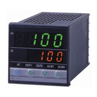
Digital Controller
Brand:
RKC INSTRUMENT
| Category:
Controller
| Size: 5 MB
Table of Contents
Table of Contents
7
1 Outline
15
Features
15
Checking the Product
15
Q&A
15
引 引 引 引
15
Model Code
16
Outline of Functions
19
2 Mounting
22
Mounting Environment
22
Mounting Cautions
22
Dimensions
23
Ha400/Ha401
23
Ha900/Ha901
23
Procedures of Mounting and Removing
24
Mounting Procedures
24
Removing Procedures
24
3 Wiring
25
Wiring Cautions
25
Terminal Layout
26
1-Input Controller
26
Wiring of each Terminal
27
Power Supply
27
Output 1 to 3 (OUT1 to OUT3)
28
Output 4 to 5 (OUT4 to OUT5)
28
Measured Input
29
Remote Input (Option)
30
Event Input (Option)
30
CT Input/Power Feed Forward Input/Feedback Resistance Input (Option)
31
Communication 1/Communication 2 (Option)
31
4 Parts Description
33
5 Setting
36
Setting Procedure to Operation
36
Operation Menu
38
Input Type and Input Range Display
39
Key Operation
40
Scrolling through Parameters
40
Changing Set Value (SV)
40
Data Lock Function
41
How to Restrict Operation of the Direct Keys
41
Changing Parameter Settings
42
Change Settings
42
6 Sv Setting & Monitor Mode
44
Display Sequence
44
Procedure for Set Value (SV) Setting
45
7 Parameter Setting Mode
46
Display Sequence
46
Parameter List
48
Description of each Parameter
49
Event 1 Set Value (EV1) Event 2 Set Value (EV2) Event 3 Set Value (EV3) Event 4 Set Value (EV4)
49
Control Loop Break Alarm (LBA) Time (Lba1, Lba2)
49
LBA Deadband (Lbd1, Lbd2)
50
Proportional Band (1. P, 2. P) for PI/PID Control
51
Integral Time (1. I, 2. I) for PI/PID Control
51
Derivative Time (1. D, 2. D) for PID Control
51
Control Response Parameter (1. Rpt, 2. Rpt)
51
Setting Change Rate Limiter (Up) (1.Svru, 2.Svru)
52
Setting Change Rate Limiter (Down) (1.Svrd, 2.Svrd)
52
Area Soak Time (AST)
53
Link Area Number (Lnka)
53
8 Setup Setting Mode
54
Display Sequence
54
Parameter List
55
Description of each Parameter
56
Heater Break Alarm 1 (HBA1) Set Value (Hba1) Heater Break Alarm 2 (HBA2) Set Value (Hba2)
56
Heater Break Determination Point 1 (Hbl1) Heater Break Determination Point 2 (Hbl2)
58
Heater Melting Determination Point 1 (Hbh1) Heater Melting Determination Point 2 (Hbh2)
58
PV Bias (1. Pb, 2. Pb)
58
PV Digital Filter (1. Df, 2. Df)
58
PV Ratio (1. Pr, 2. Pr)
59
PV Low Input Cut-Off (1. PLC, 2. PLC)
59
Proportional Cycle Time (1. T, 2. T)
59
Device Address 1 (Slave Address 1) (Add1)
60
Communication Speed 1 (Bps1)
60
Data Bit Configuration 1 (Bit1)
60
Interval Time 1 (Int1)
61
Device Address 2 (Slave Address 2) (Add2)
61
Communication Speed 2 (Bps2)
61
Data Bit Configuration 2 (Bit2)
62
Interval Time 2 (Int2)
62
Set Lock Level (LCK)
63
9 Engineering Mode
64
Display Sequence
64
Parameter List
68
Precaution against Parameter Change
72
Screen Configuration (F10)
77
STOP Display Selection (SPCH)
77
Bar Graph Display Selection (De)
78
Bar Graph Resolution Setting (Deut)
78
Direct Key (F11)
79
Auto/Manual Transfer Key Operation Selection (Fn1)
79
Remote/Local Transfer Key Operation Selection (Fn2)
79
RUN/STOP Transfer Key Operation Selection (Fn3)
79
Input 1 (F21)/Input 2 (F22)
80
Input Type Selection (1. Inp, 2. Inp)
80
Display Unit Selection (1. Unit, 2. Unit)
81
Decimal Point Position (1. Pgdp
81
Input Scale High (1. PGSH
81
Input Scale Low (1. PGSL
82
Input Error Determination Point (High Limit) (1. Pov, 2. Pov)
82
Input Error Determination Point (Low Limit) (1. Pun, 2. Pun)
82
Burnout Direction (1. Bos, 2. Bos)
83
Square Root Extraction Selection (1. Sqr, 2. Sqr)
83
Power Supply Frequency Selection (Pfrq)
83
Event Input (F23)
84
Event Input Logic Selection (Disl)
84
Output (F30)
86
Output Logic Selection (Logc)
86
Output Timer Setting (Ott1 to Ott5)
87
Transmission Output 3 (F33)
88
Transmission Output Type Selection (Ao1, Ao2, Ao3)
88
Transmission Output Scale High (AHS1, AHS2, AHS3)
88
Transmission Output Scale Low (ALS1, ALS2, ALS3)
88
Event 1 (F41)/Event 2 (F42)/Event 3 (F43)/Event 4 (F44)
89
Event Type Selection (ES1, ES2, ES3, ES4)
89
Event Hold Action (Eho1, Eho2, Eho3, Eho4)
91
Event Differential Gap (EH1, EH2, EH3, EH4)
92
Action at Event Input Error (Eeo1, Eeo2, Eeo3, Eeo4)
93
Event Assignment (EVA1, EVA2, EVA3, EVA4)
93
Current Transformer (CT1) Input (F45)
94
Current Transformer (CT2) Input (F46)
94
CT Ratio (Ctr1, Ctr2)
94
Heater Break Alarm (HBA) Type Selection (Hbs1, Hbs2)
94
Number of Heater Break Alarm (HBA) Delay Times (Hbc1, Hbc2)
95
CT Assignment (CTA1, CTA2)
95
Control (F50)
96
Hot/Cold Start Selection (Pd)
96
Input 2_Use Selection (CAM)
96
Cascade Ratio (Car)
96
Cascade Bias (Cab)
97
SV Tracking (Trk)
98
Control 1 (F51)/Control 2 (F52)
99
Control Action Type Selection (1. Os, 2. Os)
99
Integral/Derivative Time Decimal Point Position (1.Iddp, 2.Iddp)
99
Derivative Gain (1. Dga, 2.Dga)
99
ON/OFF Action Differential Gap (Upper) (1. Ohh, 2. Ohh)
100
ON/OFF Action Differential Gap (Lower) (1. Ohl, 2. Ohl)
100
Action at Input Error (High Limit) (1.Aove, 2.Aove)
101
Action at Input Error (Low Limit) (1.Aune, 2.Aune)
101
Manipulated Output Value at Input Error (1. PSM, 2.PSM)
101
Output Change Rate Limiter (Up) (1. Oru, 2. Oru)
102
Output Change Rate Limit (Down) (1. Ord, 2. Ord)
103
Output Limiter (High Limit) (1. Olh, 2. Olh)
103
Output Limiter (Low Limit) (1. Oll, 2. Oll)
103
Power Feed Forward (1. PFF, 2. PFF)
104
Power Feed Forward Gain (1. PFFS, 2. PFFS)
105
Autotuning 1 (AT1) (F53)/Autotuning 2 (AT2) (F54)
105
AT Bias (1. Atb, 2. Atb)
105
AT Cycle (1. ATC, 2. ATC)
106
AT Differential Gap Time (1. ATH, 2. ATH)
107
Position Proportioning PID Action (F55)
108
Open/Close Output Neutral Zone (Ydb)
108
Open/Close Output Differential Gap (YHS)
109
Action at Feedback Resistance (FBR) Input Error (Ybr)
109
Feedback Resistance (FBR) Input Assignment (Posa)
109
Feedback Adjustment Preparation Screen (Pos)
110
Communication Function (F60)
111
Communication Protocol Selection (CMPS1, CMPS2)
111
Set Value (SV) (F70)
111
Setting Change Rate Limiter Unit Time (Svrt)
111
Soak Time Unit Selection (Stdp)
111
Set Value 1 (SV1) (F71)/Set Value 2 (SV2) (F72)
112
Setting Limiter (High Limit) (1. SLH, 2. SLH)
112
Setting Limiter (Low Limit) (1. SLL, 2. SLL)
112
System Information Display (F91)
113
10 Operation
114
Control RUN and STOP
114
Operation under Control RUN Mode
114
Display at Control STOP
114
Configuration of Operation Mode
115
Monitoring Display in Operation
116
Autotuning (AT)
119
Requirements for at Start
119
AT Cancellation
119
Auto/Manual Transfer
120
Auto/Manual Transfer by Front Key Operation
120
Auto/Manual Transfer by Direct Key (A/M) Operation
121
Auto/Manual Transfer by Event Input
121
Procedure for Setting the Manipulated Output Value (MV) in Manual Mode
121
Remote/Local Transfer
122
Remote/Local Transfer by Front Key Operation
122
Remote/Local Transfer by Direct Key (R/L) Operation
122
Remote/Local Transfer by Event Input
123
RUN/STOP Transfer
123
RUN/STOP Transfer by Front Key Operation
123
RUN/STOP Transfer by Direct Key (R/S) Operation
124
RUN/STOP Transfer by Event Input
124
Control Area Transfer
125
Control Area Transfer by Front Key Operation
125
Control Area Transfer by Event Input
125
Start Operation When Power Failure Recovers
126
Ramp/Soak Control
127
11 Error Displays
131
Overscale and Underscale
131
Self-Diagnostic Error
132
12 Troubleshooting
133
Display
133
Control
134
Operation
135
Other
136
13 Removing the Internal Assembly
137
APPENDIX A. Setting Data List
138
A-1. SV Setting & Monitor Mode
138
A-2. Setup Setting Mode
140
A-3. Parameter Setting Mode
143
A-4. Engineering Mode (F10 to F91)
145
Specifications
164
Trans Dimensions for Power Feed Forward
171
Current Transformer (CT) Dimensions
172
Memory Area Data List
173
Advertisement
RKC INSTRUMENT HA900 Series Connection Manual (292 pages)
Temperature Controller Driver
Brand:
RKC INSTRUMENT
| Category:
Temperature Controller
| Size: 8 MB
Table of Contents
Table of Contents
1
System Configuration
11
Selection of External Device
11
Example of Communication Setting
12
Setup Items
104
Cable Diagram
109
Supported Device
211
Device Code and Address Code
286
Error Messages
292
RKC INSTRUMENT HA900 Series Communication Instruction Manual (210 pages)
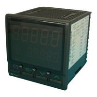
Digital Controller
Brand:
RKC INSTRUMENT
| Category:
Controller
| Size: 3 MB
Table of Contents
Table of Contents
5
1 Outline
7
2 Specifications
8
3 Wiring
11
Connect the Communication 1
11
Connect the Communication 2
14
4 Setting
19
Transfer to Setup Setting Mode
20
Setting the Communication Parameters
21
Communication Requirements
27
5 Rkc Communication
29
Polling
29
Polling Procedures
30
Polling Procedure Example
34
Selecting
35
Selecting Procedures
35
Selecting Procedure Example
39
Examples of Polling and Selecting Check Programs
40
Example of Temperature Set Values Polling Check Program
40
Example of Temperature Set Values Selecting Checking Program
42
Communication Items List
44
6 Modbus
63
Message Format
63
Function Code
64
Communication Mode
64
Slave Responses
65
Calculating CRC-16
66
Message Format
69
Read Holding Registers [03H]
69
Preset Single Register [06H]
70
Diagnostics (Loopback Test) [08H]
71
Preset Multiple Registers [10H]
72
Data Configuration
73
Data Scale
73
Caution for Handling Communication Data
77
Data Map List
78
7 Communication Data Description
105
8 Troubleshooting
205
9 Ascii 7-Bit Code Table
208
Advertisement
RKC INSTRUMENT HA900 Series Instruction Manual (170 pages)
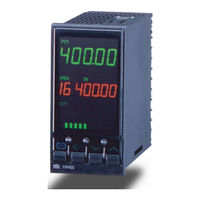
Digital Controller
Brand:
RKC INSTRUMENT
| Category:
Controller
| Size: 2 MB
Table of Contents
Table of Contents
5
Outline
7
Product Outline
7
Communication Ports
7
Specifications
8
Connection to Plc
10
Setting
12
Setting of Number of Occupied Station/Extended Cyclic
12
Transfer to Engineering Mode
13
Number of Occupied Station/Extended Cyclic Setting (Communication 2 Protocol Selection)
14
Setting of Station Number and Communication Speed
16
Transfer to Setup Setting Mode
17
Station Number (Device Address 2) and Communication Speed 2 Setting
18
CC-Link COMMUNICATION
20
Communication between Master Station and Controller
20
(Remote Device Station)
20
Processing of Numeric Data Values
22
Remote Input/Output
23
1Station Occupied 1 Time
24
Station Occupied 4 Times
27
Station Occupied 8 Times or 4 Stations Occupied 1 Time
31
Remote Register
36
Station Occupied 1 Time
37
Station Occupied 4 Times or 4 Stations Occupied 1 Time
38
Station Occupied 8 Times
41
Setting of Extension Number and Memory Area Number
46
CC-Link Flag Operation
49
Extension Number
52
Communication Data Description
69
Usage Example
152
Handling Procedures
152
System Configuration
153
CC-Link Communication Setting
154
Device Assignments Example
156
Sample Program
159
Troubleshooting
164
CC-Link Communication Status Display
165
Solutions for Problems
167
RKC INSTRUMENT HA900 Series Connection Manual (158 pages)
Temperature Controller MODBUS SIO Driver
Brand:
RKC INSTRUMENT
| Category:
Controller
| Size: 4 MB
Table of Contents
Table of Contents
1
System Configuration
3
Selection of External Device
9
Example of Communication Setting
10
Setup Items
70
Cable Diagram
75
Supported Device
144
Device Code and Address Code
155
Error Messages
157
RKC INSTRUMENT HA900 Series Instruction Manual (2 pages)
Digital Controller High-speed AT type & Standard AT type
Brand:
RKC INSTRUMENT
| Category:
Controller
| Size: 0 MB
Advertisement
Related Products
RKC INSTRUMENT HA430
RKC INSTRUMENT HA930 Series
RKC INSTRUMENT HA400 Series
RKC INSTRUMENT HA401 Series
RKC INSTRUMENT HA901 Series
RKC INSTRUMENT H-PCP-J
RKC INSTRUMENT CB Series
RKC INSTRUMENT CB100 Series
RKC INSTRUMENT CB100L
RKC INSTRUMENT CB103
RKC INSTRUMENT Categories
Temperature Controller
Controller
Media Converter
Measuring Instruments
Control Systems
More RKC INSTRUMENT Manuals
Login
Sign In
OR
Sign in with Facebook
Sign in with Google
Upload manual
Upload from disk
Upload from URL