
Subscribe to Our Youtube Channel
Related Manuals for RKC INSTRUMENT HA430


Summary of Contents for RKC INSTRUMENT HA430
- Page 1 Resin Pressure Digital Controller HA430/HA930 Operation Manual IMR01N12-E7 RKC INSTRUMENT INC.
- Page 2 CC-Link is a registered trademark of Mitsubishi Electric Co. Ltd. Company names and product names used in this manual are the trademarks or registered trademarks of the respective companies. All Rights Reserved, Copyright 2003, RKC INSTRUMENT INC.
- Page 3 Thank you for purchasing this RKC product. In order to achieve maximum performance and ensure proper operation of the instrument, carefully read all the instructions in this manual. Please place the manual in a convenient location for easy reference. NOTICE ...
- Page 4 CAUTION This product is intended for use with industrial machines, test and measuring equipment. (It is not designed for use with medical equipment and nuclear energy plant.) This is a Class A instrument. In a domestic environment, this instrument may cause radio interference, in which case the user may be required to take additional measures.
- Page 5 If you do not have a necessary manual, please contact RKC sales office, the agent, or download from the official RKC website. Manual Manual Number Remarks HA430/HA930 Instruction Manual IMR01N11-E This manual is enclosed with instrument. This manual explains the mounting and wiring, front panel name, and the operation mode outline.
- Page 6 SYMBOLS Safety Symbols : This mark indicates precautions that must be taken if there is danger of electric WARNING shock, fire, etc., which could result in loss of life or injury. : This mark indicates that if these precautions and operating procedures are not CAUTION taken, damage to the instrument may result.
-
Page 7: Table Of Contents
1.4 Parts Description ..................... 7 2. MOUNTING ................. 10 2.1 Mounting Cautions ..................10 2.2 Dimensions ....................11 HA430 ........................11 HA930 ........................11 2.3 Procedures of Mounting and Removing ............12 Mounting procedures ....................12 Removing procedures ..................... 12 3. - Page 8 Page 4. SETTING ................22 4.1 Setting Procedure to Operation ..............22 4.2 Operation Menu ..................... 24 Input type and input range display ................25 4.3 Key Operation ....................26 Scrolling through parameters................... 26 Changing Set value (SV) ..................26 ...
- Page 9 Page 7. SETUP SETTING MODE ............ 42 7.1 Display Sequence ..................42 7.2 Parameter List ....................43 7.3 Description of Each Parameter ..............44 PV bias (1. Pb, 2. Pb) ....................44 PV digital filter (1. dF, 2. dF) ..................44 ...
- Page 10 Event assignment (EVA1, EVA2, EVA3, EVA4) ............84 8.11 Control (F50) * ..................... 85 Hot/Cold start selection (Pd) ..................85 Input 2_use selection (CAM) ................... 85 SV tracking (TrK) ....................86 The setting items “CAr” and “CAb” are not used in the HA430/930. IMR01N12-E7...
- Page 11 (1. oLL, 2. oLL) ............... 92 MV transfer function (1. MVTS, 2. MVTS) ............... 92 The setting items “1.PFF,” “1.PFFS,” “2.PFF” and “2.PFFS” are not used in the HA430/930. 8.13 Autotuning 1 (AT1) (F53) /Autotuning 2 (AT2) (F54) ......93 ...
- Page 12 Page 9.3 Monitoring Display in Operation ..............102 9.4 Auto/Manual Transfer .................. 108 Auto/Manual transfer by Front key operation ............108 Auto/Manual transfer by Direct key (A/M) operation ..........109 Auto/Manual transfer by Event input ..............109 ...
- Page 13 Page APPENDIX A. Setting Data List ............. A-1 A-1. SV setting & Monitor mode ................ A-1 A-2. Setup setting mode ..................A-2 A-3. Parameter setting mode ................A-5 A-4. Engineering mode (F10 to F91) ..............A-7 B. Specifications..............A-24 C. Memory Area Data List ..........A-29 INDEX ..................
- Page 14 MEMO i-12 IMR01N12-E7...
-
Page 15: Outline
Pressure and Temperature control with a single instrument The HA430/930 provide dual loop control with a single instrument. The first loop is assigned to a strain gauge input and the second loop to a temperature input (TC, RTD, Voltage, or Current). -
Page 16: Model Code
Check whether the delivered product is as specified by referring to the following model code list. If the product is not identical to the specifications, please contact RKC sales office or the agent. HA430 −□ □−□ □−□*□ □−□ □−□/Y HA930... - Page 17 1. OUTLINE (4) Output 2 (OUT2) N : None T : Triac output 6 : Voltage output (1 to 5 V DC) M : Relay contact output 4 : Voltage output (0 to 5 V DC) 7 : Current output (0 to 20 mA DC) V : Voltage pulse output 5 : Voltage output (0 to 10 V DC) 8 : Current output (4 to 20 mA DC)
-
Page 18: Input/Output Functions
1. OUTLINE 1.3 Input/Output Functions This section describes the input/output functions of the instrument. To learn how to set each function, refer to the respective page. INPUT In addition to measured input, 2 optional input functions are available. Input 1 can be used for pressure sensor input or voltage/current input. Measured input: (Specify when ordering) ... - Page 19 1. OUTLINE OUTPUT Up to five outputs are available. They may be used as Control output, Event output or Transmission output by specifying the output type or by activating the output logic function (output logic selection). Output1 to 3 (OUT1 to OUT3): ...
- Page 20 1. OUTLINE Output logic function: Output logic function allocates output functions to output terminals. Logic output such as OR/AND is available for event output. The following signals are allocated by output logic function. Transmission output needs to be allocated separately. (Refer to P. 73 to 76.) Input Analog signal: Control output value (max.
-
Page 21: Parts Description
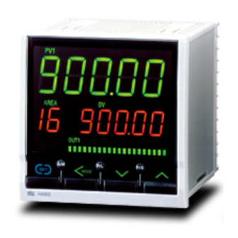
1. OUTLINE 1.4 Parts Description This section describes various display units and the key functions. HA430 PV1 PV2 MAN REM AT Upper display AREA PV2 Lower display Area display Output/Alarm lamp OUT1 OUT2 OUT3 OUT4 OUT5 ALM Infrared port Bar gragh display... - Page 22 When the Deviation display is selected, the dots at both ends of bar-graph light. [Example] * The number of dots: 10 dots (HA430) 20 dots (HA930) Bar graph display can be selected in the Engineering ode. Refer to selecting the bar graph display (P. 63).
- Page 23 1. OUTLINE Direct keys Auto/Manual transfer key Switching the Auto/Manual control mode between Auto (PID control) mode and Manual mode. Remote/Local transfer key Switching the Remote/Local control mode between Remote control and Local control. RUN/STOP transfer key Switching the RUN/STOP mode between RUN and STOP. To avoid damage to the instrument, never use a sharp object to press keys.
-
Page 24: Mounting
2. MOUNTING This chapter describes installation environment, mounting cautions, dimensions and mounting procedures. WARNING To prevent electric shock or instrument failure, always turn off the power before mounting or removing the instrument. 2. 1 Mounting Cautions (1) This instrument is intended to be used under the following environmental conditions. (IEC 61010-1) [OVERVOLTAGE CATEGORY II, POLLUTION DEGREE 2] (2) Use this instrument within the following environment conditions: ... -
Page 25: Dimensions
*3 When controllers are closely mounted, ambient temperature must not exceed 50 C (122F). For mounting of the HA430 or HA930, panel thickness must be between 1 to 10 mm. When mounting multiple HA430s or HA930s close together, the panel strength should be checked to ensure proper support. -
Page 26: Procedures Of Mounting And Removing
2. MOUNTING 2.3 Procedures of Mounting and Removing Mounting procedures 1. Prepare the panel cutout as specified in 2.2 Dimensions. Fig. 1 (Panel thickness: 1 to 10 mm) 2. Insert the instrument through the panel cutout. 3. Insert the mounting bracket into the mounting groove of the instrument. Do not push the mounting bracket forward. -
Page 27: Wiring
3. WIRING This chapter describes wiring cautions, wiring layout and wiring of terminals. WARNING To prevent electric shock or instrument failure, do not turn on the power until all wiring is completed. Make sure that the wiring is correct before applying power to the instrument. -
Page 28: Terminal Layout
3. WIRING 3.2 Terminal Layout The terminal layout is as follows. HA430 Optional Communication Power supply voltage (RKC communication/Modbus/PROFIBUS/ 100 to 240 V AC DeviceNet/CC-Link) 24 V AC 24 V DC Output 5 (OUT5) Input 1 (pressure sensor input) -
Page 29: Wiring Of Each Terminal
Power consumption 90 to 264 V AC [Including power supply voltage variation] HA430: 16.5 VA max. (at 100 V AC), 22.5 VA max. (at 240 V AC) (Rating 100 to 240 V AC), 50/60 Hz HA930: 17.5 VA max. (at 100 V AC), 24.0 VA max. (at 240 V AC) 21.6 to 26.4 V AC [Including power supply voltage variation]... -
Page 30: Output 1 To 3 (Out1 To Out3)
3. WIRING Output 1 to 3 (OUT1 to OUT3) Terminal 11 and 12 are for output 1 (OUT1); Terminal 9 and 10 are for output 2 (OUT2); and Terminal 7 and 8 are for output 3 (OUT3). Connect an appropriate load according to the output type. Relay contact output: Triac output OUT1... -
Page 31: Input 1 (Pressure Sensor Input)
Directly connect the pressure sensor (without amplifier) connection cable to terminal numbers 14 to 18, 23 and 24. As for the sensor cable connection, refer to the instruction manual for Pressure sensor used. Wiring example: Connection to our CZ-100P or CZ200P HA430/930 Shield Shield EXC... -
Page 32: Input 1 (Voltage And Current Inputs)
Sensor power supply () supply Sensor connection cable Resin pressure sensor with amplifier HA430/930 Sensor output signal () * Be sure to insulate the unused cable end. Voltage input (Input 1) In addition, conduct such treatment as not shorting nor 0 to 5 V DC Sensor output signal () -
Page 33: Input 2 (Thermocouple, Rtd, Voltage, And Current Inputs)
3. WIRING Input 2 (thermocouple, RTD, voltage, and current inputs) Input 2 can be used for the thermocouple, RTD, voltage, or current input. For the Input 2, terminals 19 to 21 are allocated to the measured input. Thermocouple Voltage input Current input... -
Page 34: Sensor Power Supply (Optional)
Sensor power supply () supply Sensor connection cable Resin pressure sensor with amplifier HA430/930 Sensor output signal () * Be sure to insulate the unused cable end. Voltage input (Input 2) In addition, conduct such treatment as not shorting nor 0 to 5 V DC Sensor output signal () - Page 35 T (B) Drain RxD/TxD-N R (A) CAN-L DGND R (B) V Example 1: Connection to the RS-232C port of the host computer (master) HA430/930 Host computer (master) RS-232C (Slave) SG (GND) SG (GND) SD (TXD) SD (TXD) RD (RXD) RD (RXD)
-
Page 36: Setting
4. SETTING This chapter describes procedures to set operating conditions of a customer and parameter of various setting modes. 4.1 Setting Procedure to Operation Conduct necessary setting before operation according to the procedure described below. Mounting and Wiring When installing the instrument, Entry to data sheet refer to 2. - Page 37 4. SETTING Continued from the previous page. To use Ramp/Soak function Parameter data setting Set parameters in Parameter setting mode: Event output/Event input function PID and control response, etc. Set the Setting change rate limiter, Area soak time and Link Up to 16 individual sets of parameters in Parameter area number.
-
Page 38: Operation Menu
4. SETTING 4.2 Operation Menu The controller has five different setting modes. All settable parameters belong to one of them. The following chart shows how to access different setting mode. For the details of key operation, refer to 4.3 Key Operation (P. -
Page 39: Input Type And Input Range Display
4. SETTING Input type and input range display This instrument immediately confirms inputs type symbol and input range following power ON. Example: When sensor type of Input 1 is pressure input, and sensor type of Input 2 is K thermocouple (2-input controller) Power ON Symbol... -
Page 40: Key Operation
4. SETTING 4.3 Key Operation Basic key operations common to each mode (set item change, set value change and registration) and Data lock function are described in the following. Scrolling through parameters Press to scroll through parameters in the same mode/area. ... -
Page 41: Data Lock Function
4. SETTING Data lock function The Data lock function limits access of unauthorized personnel to the parameters and prevents parameter change by mistake. There are 8 set data lock levels. The set data lock level can be set in Setup setting mode. Character display Parameters which can be changed Set value... -
Page 42: Changing Parameter Settings
4. SETTING 4.4 Changing Parameter Settings Procedures to change parameter settings are shown below. Change Settings Example: Change the Set value 1 (SV1) of Input 1 from 0.0 MPa to 200.0 MPa 1. Go to the mode in which the parameter is displayed If the current mode is not SV setting &... - Page 43 4. SETTING 3. Shift the high-lighted digit The high-lighted digit indicates which digit can be set. Press the shift key to high-light the hundreds digit. MODE MODE 4. Change the set value Press the UP key to change the number to 2. MODE MODE 5.
-
Page 44: Sv Setting & Monitor Mode
5. SV SETTING & MONITOR MODE 5.1 Display Sequence In SV setting & Monitor mode, the following operations are possible. Change the Set value (SV) Change Memory Area Monitor the Measured value (PV) and the Manipulated value (MV), etc. When the power is turned on, the controller goes to this mode after self-diagnostics. Use this mode during normal operation. -
Page 45: Procedure For Set Value (Sv) Setting
5. SV SETTING & MONITOR MODE 5.2 Procedure for Set Value (SV) Setting Up to 16 individual sets of SVs and parameters in Parameter setting mode can be stored and used in Multi-memory area function. Some examples of changing the Set value (SV) described in the following. The same setting procedure applies when parameters corresponding to the Multi-memory area function are also set. -
Page 46: Parameter Setting Mode
6. PARAMETER SETTING MODE 6.1 Display Sequence In Parameter setting mode, the following operations are possible. Set parameters relating to control such as PID constants, Event set values, and the Setting change rate limiter. To go to Parameter setting mode, press and hold the SET key for 2 seconds at SV setting &... - Page 47 6. PARAMETER SETTING MODE From Input 1_control response parameter setting screen SET key Input 2_proportional band Multi-memory area function: Multi-memory area function can store up to 16 individual sets of AREA SVs and parameters in Parameter setting mode. (P.37) One of the Areas is used for control, and the currently selected SET key area is “Control Area”.
-
Page 48: Parameter List
6. PARAMETER SETTING MODE 6.2 Parameter List Parameter Page Parameter Page Event 1 set value P. 35 Input 1_setting change P. 38 (EV1) rate limiter (up) (1.SVrU) Event 2 set value P. 35 Input 1_setting change P. 39 (EV2) rate limiter (down) (1.SVrd) Event 3 set value P. -
Page 49: Description Of Each Parameter
6. PARAMETER SETTING MODE 6.3 Description of Each Parameter Event 1 set value (EV1) Event 2 set value (EV2) Event 3 set value (EV3) Event 4 set value (EV4) EV1 to EV4 are set values of the Event action. Deviation: Input span to Input span Data range: Process:... -
Page 50: Lba Deadband (Lbd1, Lbd2)
6. PARAMETER SETTING MODE LBA deadband (Lbd1, Lbd2) The LBA deadband gives a neutral zone to prevent the Control loop break alarm (LBA) from malfunctioning caused by disturbance. Data range: 0.0 to Input span (Varies with the setting of the Decimal point position) Factory set value: 0.0 LBA Deadband function: The LBA may malfunction due to external disturbances. -
Page 51: Proportional Band (1. P, 2. P) For Pi/Pid Control
6. PARAMETER SETTING MODE Proportional band (1. P, 2. P) for PI/PID control 0.0 to 1000.0 of input span Data range: Pressure sensor input: 0 (0.0, 0.00) to Input span (Unit: C [F]) TC/RTD inputs: (Varies with the setting of the Decimal point position) Voltage (V)/Current (I) inputs: 0.0 to 1000.0 ... -
Page 52: Control Response Parameter (1. Rpt, 2. Rpt)
6. PARAMETER SETTING MODE Control response parameter (1. rPT, 2. rPT) The control response for the Set value (SV) change can be selected among Slow, Medium, and Fast. Data range: 0: Slow 1: Medium 2: Fast Factory set value: Input 1_control response parameter (1. -
Page 53: Setting Change Rate Limiter (Down) (1.Svrd, 2.Svrd)
6. PARAMETER SETTING MODE Setting change rate limiter (down) (1.SVrd, 2.SVrd) This function is to allow the Set value (SV) to be automatically changed at specific rates when a new Set value (SV). SVrd is used when the SV is changed to a lower SV. Data range: OFF (Unused) 0.1 to Input span/unit time... -
Page 54: Area Soak Time (Ast)
6. PARAMETER SETTING MODE Area soak time (AST) Area soak time is used for Ramp/Soak control function in conjunction with Link area number and Setting change rate limiter (up/down). Data range: 0 hour 00.00 second to 9 minutes 59.99 seconds or 0 hour 00 minute 00 second to 9 hours 59 minutes 59 seconds Factory set value: 0.00.00 (0 minute 00.00 second) -
Page 55: Link Area Number (Lnka)
6. PARAMETER SETTING MODE Link area number (LnKA) Link area number is used for Ramp/Soak control function in conjunction with Area soak time and Setting change rate limiter (up/down). Data range: OFF (No link) 1 to 16 Factory set value: Related parameters: Setting change rate limiter (up) (P. -
Page 56: Setup Setting Mode
7. SETUP SETTING MODE 7.1 Display Sequence In Setup setting mode, the following operations are possible. Change other operation/control related parameters Change Communication parameters Change Data lock level To go to Setup setting mode from SV setting & Monitor mode, press the shift key while pressing the SET key. SV setting &... -
Page 57: Parameter List
7. SETUP SETTING MODE 7.2 Parameter List Parameter Page Parameter Page Input 1_PV bias P. 44 Auto-zero P. 48 (1. Pb) (AZEr) Input 1_PV digital P. 44 Auto calibration P. 49 filter (1. dF) (ACAL) Input 1_PV ratio P. 44 Set lock level P. -
Page 58: Description Of Each Parameter
7. SETUP SETTING MODE 7.3 Description of Each Parameter PV bias (1. Pb, 2. Pb) PV bias adds bias to the Measured value (PV). The PV bias is used to compensate the individual variations of the sensors or correct the difference between the Measured value (PV) of other instruments. Input span to Input span Data range: Factory set value:... -
Page 59: Pv Low Input Cut-Off (1. Plc, 2. Plc)
7. SETUP SETTING MODE PV low input cut-off (1. PLC, 2. PLC) PV low input cut-off is used with Square root extraction function. The measured value less than the PV low input cut-off is ignored to prevent control disturbance caused by input variation at low measured value range. Data range: 0.00 to 25.00 % of input span Factory set value:... -
Page 60: Device Address (Slave Address) (Add2)
9.6 (RKC communication, Modbus) 125 (DeviceNet) 156 (CC-Link) Set the same communication speed for both the HA430/930 (slave) and the host computer (master). Communication speed is not necessary to be selected for PROFIBUS. Data bit configuration (bIT2) This item is Data bit configuration of Communication function (optional). -
Page 61: Interval Time (Int2)
0 to 250 ms Factory set value: Interval Time function: The interval time for the HA430/930 should be set to provide a time for host computer to finish sending all data including stop bit and switch the line to receive status for the host. -
Page 62: Auto-Zero (Azer)
7. SETUP SETTING MODE Auto-zero (AZEr) Adjust the zero point of the Measured value (PV1) on the Input 1 side. Factory set value: Related parameters: PV bias (P. 44) Adjustment procedure: 1. Make sure that the pressure sensor * is installed on the equipment. 3. -
Page 63: Auto Calibration (Acal)
7. SETUP SETTING MODE Auto calibration (ACAL) Adjust the full scale point of the Measured value (PV1) on the Input 1 side. Factory set value: Related parameters: PV ratio (P. 44), Shunt resistance output value (P. 68) Adjustment procedure: 1. -
Page 64: Engineering Mode
Parameters in Engineering mode are settable only when the controller is in STOP mode. Function blocks and setting items which do not exist in the HA430/930 are displayed on the screen of the shaded section. For these functions blocks and setting items, use their factory set values with these values left intact. - Page 65 8. ENGINEERING MODE Continued from the previous page. (Input 2) UP or DOWN Event input (Event input) logic selection SET key SET key (P. 73) UP or DOWN Output logic Output 1 timer Output 2 timer Output 3 timer Output 4 timer Output 5 timer (Output) selection...
- Page 66 8. ENGINEERING MODE Continued from the previous page. UP or DOWN SET key SET key SET key SET key SET key UP or DOWN SET key SET key SET key SET key SET key UP or DOWN Hot/Cold start Input 2_ (Control) selection use selection...
- Page 67 8. ENGINEERING MODE Continued from the previous page. (AT1) UP or DOWN Input 2_AT differential (AT2) Input 2_AT bias Input 2_AT cycle gap time Input 2_AT action SET key SET key SET key SET key SET key (P. 93) UP or DOWN SET key SET key SET key...
-
Page 68: Parameter List
8. ENGINEERING MODE 8.2 Parameter List Function block Parameter Page Screen STOP display selection P. 63 (SPCH) (F10.) configuration Bar graph display selection (dE) Bar graph resolution setting P. 64 (dEUT) Decimal point position of MV scaling (MVdP) MV scaling high (MVHS) MV scaling low P. - Page 69 Output 4 timer setting (oTT4) Output 5 timer setting (oTT5) Alarm lamp lighting condition setting 1 (ALC1) This item is not used for the HA430/930. (ALC2) Interlock function P. 78 (oTIL) Transmission Transmission output 1 type selection P. 79 (Ao1) (F31.)
- Page 70 (EH4) Event 4 action at input error P. 84 (EEo4) Event 4 assignment (EVA4) These are function blocks unused in the HA430/930. (F45.) (Their settings are invalid) These are function blocks unused in the HA430/930. (F46.) (Their settings are invalid)
- Page 71 P. 91 (2. ord) Input 2_output limiter high P. 92 (2. oLH) Input 2_output limiter low (2. oLL) These items are not used for the HA430/930. (2. PFF) (2.PFFS) Input 2_MV transfer function P. 92 (2.MVTS) Autotuning 1 Input 1_AT bias P.
-
Page 72: Precaution Against Parameter Change
8. ENGINEERING MODE 8.3 Precaution Against Parameter Change If any of the following parameters is changed, the set values of relevant parameters are initialized or is automatically converted according to the new setting. It may result in malfunction or failure of the instrument. - Input Type Selection of Input 1 (1. - Page 73 8. ENGINEERING MODE Continued from the previous page. Default value Pressure Voltage/ Mode Description sensor TC input RTD input current input input Transmission output 1 scale low Measured value (PV) and Set value (SV): Input scale low Manipulated output value (MV): 0.0 Engineering Transmission output 2 scale low Deviation: Input span...
- Page 74 8. ENGINEERING MODE When any one of the following parameters’ settings are changed, - Event 1 Type Selection (ES1) - Event 2 Type Selection (ES2) - Event 3 Type Selection (ES3) - Event 4 Type Selection (ES4) all parameter settings shown in the table below will be changed to Factory Default Values according to the new setting.
- Page 75 8. ENGINEERING MODE When any one of the following parameters’ settings are changed, - Input 1_Decimal Point Position (1.PGdP) - Input 2_Decimal Point Position (2.PGdP) all parameter settings shown in the table below will be automatically converted into the a values to match the new decimal point position as long as the converted values are in the acceptable range of each parameter.
- Page 76 8. ENGINEERING MODE Continued from the previous page. Precaution and Example of automatic conversion Decimal point position moves in accordance with the setting change. Example: When the setting of the decimal point position is changed from 0 (no decimal place) to 1 (the first decimal place) with Input scale high (1.PGSH) set to 250 MPa: (1.PGSH) (1.PGSH)
-
Page 77: Screen Configuration (F10)
8. ENGINEERING MODE 8.4 Screen Configuration (F10) STOP display selection (SPCH) STOP message for control STOP mode can be displayed either on the upper display or the lower display. SPCH is to select the display to show the STOP message. Data range: 0: Displays on the Measured value (PV1/PV2) unit (TYPE 1) 1: Displays on the Set value (SV) unit (TYPE 2) -
Page 78: Bar Graph Resolution Setting (Deut)
[Display example] The number of dot points: 10 dots (HA430) 20 dots (HA930) Bar graph resolution setting (dEUT) Use to set the bar graph display resolution for the deviation display. Set several digits per 1 dot of the bar graph. -
Page 79: Mv Scaling Low (Mvls)
8. ENGINEERING MODE MV scaling low (MVLS) This value is to set the low limit value of MV scaling monitor value. Set the motor RPM when MV1 = 0 %. 9 to 9999.9 Data range: 1999 Factory set value: Related parameters: Decimal point position of MV scaling (P. -
Page 80: Input 1 (F21)/Input 2 (F22)
8. ENGINEERING MODE 8.6 Input 1 (F21) Input 2 (F22) Input type selection (1. InP, 2. InP) Data range: Input 1_input type selection (1. InP): 14 to 29 (22, 23: Not available) [Input Range Table] Set value Input type Input range Hardware Voltage... -
Page 81: Display Unit Selection (1. Unit, 2. Unit)
1.234 C 97J21020 DATE 9710 RKC INSTRUMENT INC. MADE IN JAPAN (Example of the rated nameplate) The rated output value (mV/V) of the CZ-100P/CZ-200P is when the cable is at a length of 5 m. If the cable is extended, correct the rated output value using the following equation. -
Page 82: Linearize Type (Lins) [F21]
DATE 97J21020 9710 linearizing type. RKC INSTRUMENT INC. MADE IN JAPAN (Example of the rated nameplate) This setting does not used to the strain gauge type sensors other than RKC product. Set it to “0” fixed. Shunt resistance output value (SHnT) [F21] When the strain gauge type sensor other than RKC product is used, it is set “What percentage of the rated... -
Page 83: Decimal Point Position (1. Pgdp
8. ENGINEERING MODE Decimal point position (1. PGdP, 2. PGdP) Use to select the decimal point position of the input range. Data range: 0: No decimal place 3: Three decimal places 1: One decimal place 4: Four decimal places 2: Two decimal places Input 1_decimal point position (1. -
Page 84: Input Scale Low (1. Pgsl
8. ENGINEERING MODE Input scale low (1. PGSL, 2. PGSL) This value is to set the low limit of the input scale range. Data range: Pressure sensor input: Minimum value of the selected input range to Input scale high TC/RTD inputs: Minimum value of the selected input range to Input scale high Voltage (V)/Current (I) inputs:... -
Page 85: Input Error Determination Point (Low) (1. Pun, 2. Pun)
8. ENGINEERING MODE Input error determination point (low) (1. PUn, 2. PUn) Use to set Input error determination point (low). Input error determination function is activated when a measured value reaches the limit, and control output value selected by Action at input error will be output. Input scale low ... -
Page 86: Square Root Extraction Selection (1. Sqr, 2. Sqr)
8. ENGINEERING MODE Square root extraction selection (1. SQr, 2. SQr) Use to select Use/Unuse of the Square root extraction for the measured value. Data range: 0: Unused 1: Used Factory set value: Input 1_square root extraction selection (1. SQr): 0 Input 2_square root extraction selection (2. -
Page 87: Event Input (F23)
8. ENGINEERING MODE 8.7 Event Input (F23) Event input logic selection (dISL) Use to assign the function (memory area, operation mode) for the Event inputs (DI 1 to DI 5). Data range: 0 to 15 (Refer to the following table) [Function Assignment Table] DI 1 DI 2... - Page 88 8. ENGINEERING MODE Continued from the previous page. Contact status of memory area number selection To store a new Memory area number as the Control area, close the DI for Memory area set. Memory area number Event input ...
- Page 89 8. ENGINEERING MODE Continued from the previous page. RUN/STOP transfer Mode select from front key Status of event input (DI) Actual operation mode STOP display or communication Contact closed RUN (Control RUN) STOP is not displayed RUN (Control RUN) Contact open Contact closed STOP (Control STOP)
-
Page 90: Output (F30)
OUT2 OUT3 OUT4 OUT5 Remarks value (M/V/R/E/T) (M/V/R/E/T) (M/V/R/E/T) This set value is not used for the HA430/930. This set value is not used for the HA430/930. EV3 (Energized) FAIL Energized alarm (Energized) (Energized) (De-energized) corresponding to EV4 (Energized) -
Page 91: Output Timer Setting (Ott1 To Ott5)
[ALC1 screen] [ALC2 screen] (1) Event 1 (6) As this screen is not used for the HA430/930, do not change 0: ALM lamp is not lit 1: ALM lamp is lit (2) Event 2 the setting. 0: ALM lamp is not lit 1: ALM lamp is lit... -
Page 92: Interlock Function (Otil)
8. ENGINEERING MODE Interlock function (oTIL) Use to select the Interlock function to output 1 (OUT1) to output 5 (OUT5). Data range: (1) Output 1 (OUT1) (4) Output 4 (OUT4) 0: Unused 1: Used 0: Unused 1: Used (2) Output 2 (OUT2) (5) Output 5 (OUT5) 0: Unused 1: Used... -
Page 93: Transmission Output 1 (F31)/ Transmission Output 2 (F32)
8. ENGINEERING MODE 8.9 Transmission Output 1 (F31) Transmission Output 2 (F32) Transmission Output 3 (F33) Transmission output type selection (Ao1, Ao2, Ao3) Use to select the transmission output type. Data range: None (2. PV): Input 2_measured value (PV) (1. -
Page 94: Event 1 (F41)/Event 2 (F42)/Event 3 (F43)/Event 4 (F44)
8. ENGINEERING MODE 8.10 Event 1 (F41) Event 3 (F43) Event 2 (F42) Event 4 (F44) Event type selection (ES1, ES2, ES3, ES4) Use to select a type of the event 1, 2, 3 and 4. Data range: 0: None 5: Process high 1: Deviation high 6: Process low... - Page 95 8. ENGINEERING MODE Continued from the previous page. Control loop break alarm (LBA) The Control loop break alarm (LBA) function is used to detect a load (heater) break or a failure in the external actuator (magnet relay, etc.), or a failure in the control loop caused by an input (sensor) break. The LBA function is activated when control output reaches 0 % (low limit with output limit function) or 100 % (high limit with output limit function).
-
Page 96: Event Hold Action (Eho1, Eho2, Eho3, Eho4)
8. ENGINEERING MODE Event hold action (EHo1, EHo2, EHo3, EHo4) Use to set a event hold action for the Event 1, 2, 3 or 4. When high alarm with Hold/Re-hold action is used for Event function, alarm does not turn on while Hold action is in operation. -
Page 97: Event Differential Gap (Eh1, Eh2, Eh3, Eh4)
8. ENGINEERING MODE Continued from the previous page. [Example] When Event 1 type is the deviation low: When Re-hold action is OFF and event output type is deviation, the event output is produced due to the Set value change. The Re-hold action suppresses the alarm output until the Measured value has entered the non-event range again. -
Page 98: Event Action At Input Error (Eeo1, Eeo2, Eeo3, Eeo4)
8. ENGINEERING MODE Event action at input error (EEo1, EEo2, EEo3, EEo4) Event action at input error is to select the Event action when the measured value reaches the Input error determination point (high or low limit). Data range: 0: Normal processing 1: Turn the event output ON Factory set value:... -
Page 99: Control (F50)
Input 2_use selection (CAM) Use to select the usage of Input 2. Data range: 0: Single loop control 1: Remote input Factory set value: The setting items “CAr” and “CAb” displayed hereafter are not used in the HA430/930. IMR01N12-E7... -
Page 100: Sv Tracking (Trk)
8. ENGINEERING MODE SV tracking (TrK) To select Use/Unuse of SV tracking. Data range: 0: Unused 1: Used Factory set value: 1 SV Tracking function: With SV Tracking function, when Remote/Local mode is transferred from Remote to Local, the set value used in Remote mode before the mode transfer will be kept using in Local mode to prevent rapid set value change. -
Page 101: Control 1 (F51) Control 2 (F52)
8. ENGINEERING MODE 8.12 Control 1 (F51) Control 2 (F52) Control action type selection (1. oS, 2. oS) Use to select Direct action/Reverse action. Data range: 0: Direct action 1: Reverse action Factory set value: Input 1_control action type selection (1. oS): 1 Input 2_control action type selection (2. -
Page 102: On/Off Action Differential Gap (Upper) (1. Ohh, 2. Ohh)
8. ENGINEERING MODE ON/OFF action differential gap (upper) (1. oHH, 2. oHH) Use to set the ON/OFF control differential gap (upper). Data range: 0 to Input span (Varies with the setting of the Decimal point position) Factory set value: Input 1_ON/OFF action differential gap (upper) (1. -
Page 103: Action At Input Error (High) (1.Aove, 2.Aove)
8. ENGINEERING MODE Action at input error (high) (1. AoVE, 2. AoVE) Use to select the action when the measured value reaches the Input error determination point (high). Data range: 0: Normal control 1: Manipulated output value at input error (PSM) Factory set value: Input 1_action at input error (high) (1. -
Page 104: Manipulated Output Value At Input Error (1. Psm, 2. Psm)
8. ENGINEERING MODE Manipulated output value at input error (1. PSM, 2. PSM) When the measured value reaches Input error determination point and Action at input error is set to “1”, this manipulated value is output. 5.0 to 105.0 % Data range: Input 1_manipulated output value at input error (1. -
Page 105: Output Change Rate Limiter (Down) (1. Ord, 2. Ord)
8. ENGINEERING MODE Continued from the previous page. [Example] The Output change rate limiter is effective. The MV reaches 100 % when the power is turned on to the controller and such a sudden output change is not acceptable in the application. ... -
Page 106: Output Limiter High (1. Olh, 2. Olh)
Description of function: Refer to Output limiter high. The setting items “1. PFF”, “1. PFFS”, “2. PFF” and “2. PFFS” displayed hereafter are not used in the HA430/930. MV transfer function (1. MVTS, 2. MVTS) The final Manipulated output value (MV) used under Manual control with the control mode transferred to Auto control from Manual control is stored to the Manipulated output value (PSM’) when transferred to Auto... -
Page 107: Autotuning 1 (At1) (F53) Autotuning 2 (At2) (F54)
8. ENGINEERING MODE 8.13 Autotuning 1 (AT1) (F53) Autotuning 2 (AT2) (F54) AT bias (1. ATb, 2. ATb) Use to set a bias to move the set value only when Autotuning (AT) is activated. Input span to Input span Data range: Factory set value: Input 1_AT bias (1. -
Page 108: At Cycle (1. Atc, 2. Atc)
8. ENGINEERING MODE AT cycle (1. ATC, 2. ATC) The number of ON/OFF cycles is selected when the Autotuning (AT) function is executed. Data range: 0: 1.5 cycles 1: 2.0 cycles 2: 2.5 cycles 3: 3.0 cycles Factory set value: Input 1_AT cycle (1. -
Page 109: At Differential Gap Time (1. Ath, 2. Ath)
Set value (SV) Time AT start AT differential gap time The factory set value of the AT cycle is 2 cycles. Function block F55 (Including setting item) displayed hereafter is not used in the HA430/930. IMR01N12-E7... -
Page 110: At Action (1. Att, 2. Att)
8. ENGINEERING MODE AT action (1. ATt, 2. ATt) Use to select the Autotuning (AT) function. Data range: 0: AT function (PID) (AT result is reflected to derivative time.) 1: AT function (PI) (No AT result is reflected to derivative time.) 2: No AT function Factory set value: Input 1_AT action (1. -
Page 111: Communication Function (F60)
8. ENGINEERING MODE 8.14 Communication Function (F60) The setting items “Car” and “Cab” displayed hereafter are not used in the HA430/930. Communication protocol selection (CMPS2) Use to select the protocol of Communication. Data range: 0: RKC communication 1: Modbus 1 (Data transfer: In order of low-order word from high-order word) -
Page 112: Set Value 1 (Sv1) (F71) Set Value 2 (Sv2) (F72)
8. ENGINEERING MODE 8.16 Set Value 1 (SV1) (F71) Set Value 2 (SV2) (F72) Setting limiter high (1. SLH, 2. SLH) Use to set a high limit of the set value. Data range: Setting limiter low to Input scale high Factory set value: Input 1_setting limiter high [1.SLH]: Input 1_input scale high Input 2_setting limiter high [2.SLH]: Input 2_input scale high... -
Page 113: System Information Display (F91)
Holding peak value ambient temperature display (TCJ) Displays the maximum ambient temperature of the instrument. Display range: 10.0 to 100.0 C Press the SET key This screen is displayed but not used for the HA430/930. Press the SET key IMR01N12-E7... -
Page 114: Operation
9. OPERATION 9.1 Control RUN and STOP There is no power switch on this instrument, and the instrument starts operation immediately following initial power-ON (Factory set value: RUN). There are parameters in Engineering mode which cannot be changed when the controller is in RUN mode. Press the direct key (R/S) to change the RUN/STOP mode from RUN to STOP when a change for the parameters in Engineering mode is necessary. -
Page 115: Configuration Of Operation Mode
9. OPERATION 9.2 Configuration of Operation Mode Display Sequence The operation mode is used to selects the operation modes (PID/AT, Auto/Manual, Remote/Local, RUN/STOP) of the instrument. Every time the SET key or the shift key is pressed, the display goes to the next parameters. SV Setting &... -
Page 116: Monitoring Display In Operation
9. OPERATION 9.3 Monitoring Display in Operation In SV setting & Monitor mode, the following operations are possible. Change the Set value (SV) Change Memory area Monitor the Measured value (PV) and the Manipulated value (MV), etc. Use this mode during normal operation. ... - Page 117 9. OPERATION Continued from the previous page. Input 2_measured value (PV2)/set value (SV2) monitor Measured value 2 (PV2) Set value 2 (SV2) AREA In the Manual operation, the Manipulated output value (MV2) of Input 2 can be set. Setting range: Input 2_output limiter low to Input 2_output limiter high OUT1 SET key When the Setting change rate limiter is set and the SV is changed, the SV changes...
- Page 118 9. OPERATION Continued from the previous page. Peak hold function: The Peak hold function is used to store (hold) the maximum (peak) measured value (PV). The peak hold value is updated regardless of the STOP or RUN state if the power to this controller is turned on.
- Page 119 9. OPERATION Continued from the previous page. Measured value (PV) Bottom hold Bottom hold Monitor value Time Display Power ON updating Hold reset Bottom hold value is not backed up. PV1 hold reset Input 1_peak and bottom hold value is reset when the UP and DOWN keys a simultaneously pressed.
- Page 120 9. OPERATION Continued from the previous page. Input 1_manipulated output value (MV1) monitor Input 1_manipulated output value (MV1) of 0 to 100 % is displayed as a value which is made scaling to the motor RPM. Display range: MV scaling low to MV scaling high Related parameters: Decimal point position of MV scaling (P.
- Page 121 9. OPERATION Continued from the previous page. Measured value (PV) Example: Process high Event set value Differential gap Event state Without interlock Non-event state Event state With interlock Non-event state Interlock release Interlock release Valid Invalid Valid Invalid...
-
Page 122: Auto/Manual Transfer
9. OPERATION 9.4 Auto/Manual Transfer The Auto/Manual transfer can be made by Event input (optional) or Communication (optional) other than the key operation. For details of Auto/Manual transfer by communication, refer to the Communication Instruction Manual (IMR01N13-E).* * Refer to Communication Instruction Manual (IMR01N14-E) for PROFIBUS, Communication Instruction Manual (IMR01N15-E) for DeviceNet, and Communication Instruction Manual (IMR01N21-E) for CC-Link. -
Page 123: Auto/Manual Transfer By Direct Key (A/M) Operation
9. OPERATION Auto/Manual transfer by Direct key (A/M) operation Every time the Auto/Manual (A/M) transfer key is pressed, the Auto mode is changed to the Manual mode alternately. AREA MAN REM AT AREA MAN REM AT Displays Input number (1 or 2) only when either Input 1 or Input 2 is OUT1... -
Page 124: Procedure For Setting The Manipulated Output Value (Mv) In Manual Mode
9. OPERATION Procedure for setting the Manipulated output value (MV) in Manual mode When the controller is in Manual mode, the Manipulated output value (MV) can be manually set. [Display example] Setting procedure 1. Make sure the Manual (MAN) mode lamp is lit. 2. -
Page 125: Remote/Local Transfer
9. OPERATION 9.5 Remote/Local Transfer The Remote/Local transfer can be made by Event input (optional) or Communication (optional) other than the key operation. For details of the Remote/Local transfer by communication, refer to the Communication Instruction Manual (IMR01N13-E).* * Refer to Communication Instruction Manual (IMR01N14-E) for PROFIBUS, Communication Instruction Manual (IMR01N15-E) for DeviceNet, and Communication Instruction Manual (IMR01N21-E) for CC-Link. -
Page 126: Remote/Local Transfer By Event Input
9. OPERATION Remote/Local transfer by Event input Remote/Local transfer by the Event input is possible with the Event input logic selection (P. 73) of the Engineering mode. The table below shows the actual operation modes and lamp status under different combinations of settings by front key, communication and Event input. -
Page 127: Run/Stop Transfer By Direct Key (R/S) Operation
9. OPERATION RUN/STOP transfer by Direct key (R/S) operation Every time the RUN/STOP (R/S) transfer key is pressed, the RUN mode is changed to the STOP mode alternately. AREA MAN REM AT AREA MAN REM AT MODE MODE RUN mode STOP mode Direct key operation setting can be changed in Engineering mode. -
Page 128: Control Area Transfer
9. OPERATION 9.7 Control Area Transfer The control area transfer can be made by Event input (optional) or Communication (optional) other than the key operation. For details of transfer by communication, refer to the Communication Instruction Manual (IMR01N13-E).* * Refer to Communication Instruction Manual (IMR01N14-E) for PROFIBUS, Communication Instruction Manual (IMR01N15-E) for DeviceNet, and Communication Instruction Manual (IMR01N21-E) for CC-Link. -
Page 129: Start Action At Recovering Power Failure
9. OPERATION 9.8 Start Action at Recovering Power Failure The operation of this instrument is not affected by a power failure of 20 ms or less. The control start mode at power recovery after more than 20 ms power failure can be selected as follows. Power failure Power failure less than 3 seconds... -
Page 130: Ramp/Soak Control
9. OPERATION 9.9 Ramp/Soak Control Ramp/Soak control is possible by using Area soak time, Link area number and Setting change rate limiter (up/down) in Parameter setting mode (P. 31). The operating procedure is described in the following. Example: Ramp/Soak control by linking Memory area 1 to 3 The following is based on assumptions described below. - Page 131 9. OPERATION 9. Press the SET key to store the new value. The display goes 16. Press the SET key until Area soak time setting screen is to the next parameter. displayed. AREA AREA Flashing Factory set value: 0.00.00 (0 min. 00.00 sec.) (Example: Event 1 set value setting screen) 10.
- Page 132 9. OPERATION 23. Press the UP key to change the number to 3. Check that STEP 2: this screen is set to OFF. Set the SV to each of Memory area 1, 2 and 3. 1. Press and hold the SET key for 2 seconds to change the mode from the Parameter Setting mode to SV setting &...
- Page 133 9. OPERATION 7. Press the shift key until the memory area display unit is 14. Press the UP key to change the number to 3. The number displayed. in AREA (Area number) display flashes. AREA AREA Memory area No. 3 High-light 8.
-
Page 134: Error Display
10. ERROR DISPLAY 10.1 Over-scale and Underscale The table below shows displays, description, control actions and solutions when the Measured value (PV) exceeds the display range. Display Description Action (Output) Solution Check input type, input Measured Input error Action at input error: range, sensor and sensor value (PV) Measured value (PV) -
Page 135: Self-Diagnostic Error
10. ERROR DISPLAY 10.2 Self-diagnostic Error Displays and description of self-diagnostics are described in the following table: Upper Lower Description Action Solution display display Display: Error display Adjusted data error Turn off the power at Output: Adjusted data range is abnormal. once. -
Page 136: Troubleshooting
11. TROUBLESHOOTING This section explains possible causes and solutions if any abnormality occurs in the instrument. For any inquiries or to confirm the specifications of the product, please contact RKC sales office or the agent. If it is necessary to replace a device, always strictly observe the warnings below. WARNING ... -
Page 137: Control
11. TROUBLESHOOTING Continued from the previous page. Problem Possible cause Solution Measured value (PV) display PV bias is set Set the PV bias to “OFF” by referring to PV bias (P. 44). However, this is differs from the actual value limited only to when the PV bias setting can be changed. -
Page 138: Operation
11. TROUBLESHOOTING Continued from the previous page. Problem Possible cause Solution Autotuning (AT) function not Requirements for performing the Satisfy the requirements for activated Autotuning (AT) function are not performing the Autotuning (AT) satisfied function by referring to AT action (P. -
Page 139: Other
11. TROUBLESHOOTING Continued from the previous page. Problem Possible cause Solution Set value (SV) does not The Setting limiter is set Change the Setting limiter setting by become more than (or less referring to 8.16 Set Value 1 than) a specific value (SV1)/Set Value 2 (SV2) (P. -
Page 140: Removing The Internal Assembly
12. REMOVING THE INTERNAL ASSEMBLY Removing the internal assembly from the case is rarely required. Should you remove the internal assembly without disconnecting the external wiring, take the following steps: WARNING To prevent electric shock or instrument failure, only qualified personnel should be allowed to pull out the internal assembly. -
Page 141: Appendix A. Setting Data List
APPENDIX A. Setting Data List A-1. SV setting & Monitor mode Factory set User set Name Parameter Data range Page value value Input 1_ The upper section: P. 30 measured value (PV1)/ Displays Input 1_PV1 P. 102 set value (SV1) monitor The lower section: Displays Input 1_SV1 ... -
Page 142: A-2. Setup Setting Mode
APPENDIX Continued from the previous page. Factory set User set Name Parameter Data range Page value value Displays the interlock status. Interlock release P. 30 Interlock status is release when the (ILr) P. 106 UP and Down keys a simultaneously pressed. - Page 143 APPENDIX Continued from the previous page. Factory set User set Name Parameter Data range Page value value Device address 0 to 99 (RKC communication, Modbus) P. 46 (Slave address) 0 to 63 (DeviceNet) (Add2) 0 to 126 (PROFIBUS) 0 to 64 (CC-Link: 1 station occupied 1 time, 1 station occupied 4 times, 1 station occupied 8 times)
- Page 144 APPENDIX Continued from the previous page. Data bit configuration Set value Data bit Parity bit Stop bit (8n1) None (8n2) None (8E1) (8E2) Even (8o1) (8o2) Even (7n1) None (7n2) None (7E1) (7E2) (7o1) Even (7o2) Even (7n1 to 7o2: Invalid for Modbus) Set lock level list Set value Parameters which can be changed...
-
Page 145: A-3. Parameter Setting Mode
APPENDIX A-3. Parameter setting mode Factory set User set Name Parameter Data range Page value value Event 1 set value Deviation: 50.0 P. 35 Input span to Input span (EV1) Process/SV: Input scale low to Input scale high Event 2 set value Deviation: 50.0 P. - Page 146 APPENDIX Continued from the previous page. Factory set User set Name Parameter Data range Page value value Input 1_control response 0: Slow P. 38 parameter 1: Medium (1. rPt) 2: Fast Input 2_ proportional band TC/RTD inputs: 30.0 P. 37 0 (0.0, 0.00) to Input span (2.
-
Page 147: A-4. Engineering Mode (F10 To F91
In Engineering mode, the function blocks (F45, F46 and F55) and setting items which do not exist in the HA430/930 are also displayed. For these function blocks and setting items, use their factory set values with these values left intact. - Page 148 APPENDIX Function block F21: Input 1 Factory set User set Name Parameter Data range Page value value Based on Input 1_input type selection Voltage (V)/Current (I) inputs P. 66 19999 to 99999 model code. (1. InP) 14: 0 to 20 mA DC 24: ±100 mV DC When not 15: 4 to 20 mA DC 25: ±10 mV DC specifying:...
- Page 149 APPENDIX Continued from the previous page. Factory set User set Name Parameter Data range Page value value Input 1_decimal point 0: No decimal place P. 69 position 1: One decimal place (1.PGdP) 2: Two decimal places 3: Three decimal places 4: Four decimal places Less than 1 MPa (Rated pressure): Decimal point position 0 to 4...
- Page 150 APPENDIX Function block F22: Input 2 Factory set User set Name Parameter Data range Page value value Input 2_input type selection TC input Based on P. 66 200 to 1372 C model code. (2. InP) 328.0 to 2501.6 F 200 to 1200 C When not 328.0 to 2192.0 F...
- Page 151 APPENDIX Continued from the previous page. Factory set User set Name Parameter Data range Page value value Input 2_decimal point 0: No decimal place P. 69 position 1: One decimal place (2.PGdP) 2: Two decimal places 3: Three decimal places 4: Four decimal places Input 2_input scale high TC/RTD inputs:...
- Page 152 APPENDIX Function block F23: Event input Factory set User set Name Parameter Data range Page value value Event input logic selection 0 to 15 P. 73 (Refer to the following table.) (dISL) Event input logic selection DI 1 DI 2 DI 3 DI 4 DI 5...
- Page 153 SV hundreds digits: 0 or 1 (OUT3) 1: Used SV tens digits 0 or 1 (OUT2) SV units digits: 0 or 1 (OUT1) * This item is not used for the HA430/930. Output logic selection Set value OUT1 OUT2 OUT3...
- Page 154 APPENDIX Function block F31: Transmission output 1 Factory set User set Name Parameter Data range Page value value Transmission output 1_ -----: None -----: None P. 79 type selection 1. PV: Input 1_ (Ao1) measured value (PV) 1. SV: Input 1_set value (SV) 1.dEV: Input 1_deviation value...
- Page 155 APPENDIX Function block F32: Transmission output 2 Factory set User set Name Parameter Data range Page value value Transmission output 2_ -----: None -----: None P. 79 type selection 1. PV: Input 1_ (Ao2) measured value (PV) 1. SV: Input 1_set value (SV) 1.dEV: Input 1_deviation value...
- Page 156 APPENDIX Function block F33: Transmission output 3 Factory set User set Name Parameter Data range Page value value Transmission output 3_ -----: None -----: None P. 79 type selection 1. PV: Input 1_ (Ao3) measured value (PV) 1. SV: Input 1_set value (SV) 1.dEV: Input 1_deviation value...
- Page 157 APPENDIX Function block F41: Event 1 Factory set User set Name Parameter Data range Page value value Event 1 type selection 0: None P. 80 1: Deviation high (ES1) 2: Deviation low 3: Deviation high/low 4: Band 5: Process high 6: Process low 7: SV high 8: SV low...
- Page 158 APPENDIX Continued from the previous page. Factory set User set Name Parameter Data range Page value value Event 2 action at input error 0: Normal processing P. 84 1: Turn the event output ON (EEo2) Event 2 assignment 1: For Input 1 P.
- Page 159 P. 85 1: Remote input (CAM) Unused * 1.0000 (CAr) Unused * (CAb) SV tracking 0: Unused P. 86 1: Used (TrK) * These items are not used for the HA430/930. A- 19 IMR01N12-E7...
- Page 160 (1. oLL) Unused * 0 or 1 (1. PFF) Unused * 1.00 (1.PFFS) Input 1_MV transfer function 0: Unused P. 92 (1.MVTS) 1: Used * These items are not used for the HA430/930. A-20 IMR01N12-E7...
- Page 161 Unused * 0 or 1 (2. PFF) Unused * 1.00 (2.PFFS) Input 2_MV transfer function 0: Unused P. 92 (2.MVTS) 1: Used * These items are not used for the HA430/930. A- 21 IMR01N12-E7...
- Page 162 10: CC-Link (1 station occupied 1 time) CC-Link: 10 11: CC-Link (1 station occupied 4 times) 12: CC-Link (1 station occupied 8 times) 13: CC-Link (4 stations occupied 1 time) * This item is not used for the HA430/930. IMR01N12-E7...
- Page 163 10.0 to 100.0 C Holding peak value ambient P. 99 temperature display Displays the maximum ambient (TCJ) temperature of the instrument. Unused * (HEAT) * This item is not used for the HA430/930. A- 23 IMR01N12-E7...
-
Page 164: Specifications
APPENDIX B. Specifications Measured input Pressure sensor input (Input 1): Specify when ordering Corresponding sensor: Strain gauge type of pressure sensor Temperature input (Input 2): Specify when ordering K, J, T, S, R, E, B, N (JIS-C1602-1995) PL II (NBS), W5Re/W26Re (ASTM-E988-96) RTD: Pt100 (JIS-C1604-1997) JPt100 (JIS-C1604-1989, JIS-C1604-1981 of Pt100) - Page 165 APPENDIX Event input (Optional) Number of inputs: Up to 5 points Input method: Dry contact input OPEN (OFF) state: 500 k or more CLOSE (ON) state: 10 or less Functions: Memory area selection, RUN/STOP transfer, Remote/Local transfer, Auto/Manual transfer, Hold reset, Interlock release, Manual output up/down (Motor RPM up/down), Manual output 0 % reset (Motor RPM reset) ...
- Page 166 APPENDIX Triac output Output method: AC output (Zero-cross method) 0.4 A (Ambient temperature 40 C or less) Allowable load current: Ambient temperature 50 C: 0.3 A Load voltage: 75 to 250 V AC Minimum load current: 30 mA ON voltage: 1.6 V or less (at maximum load current) ...
- Page 167 APPENDIX Hold function Hold type: Peak hold, Bottom hold Event output function Number of calculations: 4 points Event type: Deviation high, Deviation low, Deviation high/low, Band, Process high, Process low, SV high, SV low, Control loop break alarm (LBA) Additional function: Hold action (Effective only when deviation or process action is selected) Event action at input error selection...
- Page 168 Absolute humidity: MAX.W.C 29 g/m dry air at 101.3 kPa Ambient atmosphere: There should be neither corrosive gases nor much dust. HA430: 48 (W) 96 (H) 100 (D) mm Dimensions: HA930: 96 (W) 96 (H) 100 (D) mm Weight: HA430: Approx.
-
Page 169: Memory Area Data List
APPENDIX C. Memory Area Data List (Copy this sheet for its use.) Sheet No. Memory area No. Date Name Display Item Set value Memo Set value 1 (SV1) Proportional band 1 Integral time 1 Derivative time 1 Control response parameter 1 Set value 1 (SV1) change rate limiter (up) Set value 1 (SV1) change rate limiter (down) Set value 2 (SV2) - Page 170 MEMO A-30 IMR01N12-E7...
-
Page 171: Index
INDEX Alphabetical order Full scale adjustment ............ 44, 49 Action at input error (high) ..........89 Action at input error (low) ............ 89 Gain setting ................ 67 Alarm (ALM) lamp ..............8 Alarm lamp lighting condition setting ........77 Area (AREA) lamp .............. - Page 172 INDEX ON/OFF action differential gap (upper) ......88 Setting limiter low ............... 98 Operation Menu ..............24 Shunt resistance output value ..........68 Output (OUT1 to OUT5) lamp ..........8 Soak time unit selection ............. 97 Output 1 to 3 (OUT1 to OUT3) ........... 16 Square root extraction selection .........
- Page 173 INDEX Required operations and functions Auto/Manual needs to be switched. Configuration of Operation Mode ........101 Auto/Manual Transfer ............ 108 Control panel needs to be designed and fabricated. Dimensions ..............11 Remote/Local needs to be switched. Wiring ................13 Configuration of Operation Mode ........
- Page 174 INDEX Start operation when power failure recovers needs to The content of bar-graph display needs to be changed. Bar graph display selection ..........63 be changed. Bar graph resolution setting ..........64 Hot/Cold start selection ........... 85 Start Operation when Power Failure Recovers ..... 115 The maximum and minimum PV values need to be monitored (reset).
- Page 175 The first edition: OCT. 2003 [IMQ00] The seventh edition: MAR. 2018 [IMQ00]...
- Page 176 RKC INSTRUMENT INC. HEADQUARTERS: 16-6, KUGAHARA 5-CHOME, OHTA-KU TOKYO 146-8515 JAPAN PHONE: 03-3751-9799 (+81 3 3751 9799) E-mail: info@rkcinst.co.jp Website: http://www.rkcinst.com/ IMR01N12-E7 MAR. 2018...
Need help?
Do you have a question about the HA430 and is the answer not in the manual?
Questions and answers