Table of Contents
Advertisement
Advertisement
Table of Contents

Subscribe to Our Youtube Channel
Related Manuals for Memmert HCP105


Summary of Contents for Memmert HCP105
- Page 1 OPERATING MANUAL HUMIDITY CHAMBER HCP...
- Page 2 91186 Büchenbach Germany Please contact our customer service department before sending appliances for repair or before returning equipment, or the shipment may be refused. © 2018 MEMMERT GmbH + Co. KG D39303 | Date 09/2018 Subject to change without notice...
- Page 3 Function and operation are identical. Other documents that have to be observed When operating the appliance with the MEMMERT AtmoCONTROL PC software, observe the separate software manual. To open the AtmoCONTROL software manual, click on “Help” in the AtmoCONTROL menu bar.
-
Page 4: Table Of Contents
Contents Contents For your safety Terms and signs used......................6 Product safety and dangers ....................7 Requirements of the operating personnel ................8 Responsibility of the owner ....................8 Intended use and improper use ..................8 Changes and alterations ...................... 9 Behaviour in case of malfunctions and irregularities ............ - Page 5 Contents Malfunctions, warning and error messages Warning messages of the monitoring function ..............37 Malfunctions, operating problems and appliance errors ..........38 Power failure ........................40 Menu mode Overview ..........................41 Basic operation in menu mode using the example of language selection ....... 42 Setup..........................
-
Page 6: For Your Safety
For your safety For your safety 1.1 Terms and signs used In this manual and on the appliance itself, certain common terms and signs are used to warn you of possible dangers or to give you hints that are important in avoiding injury or damage. Observe and follow these notes and regulations to avoid accidents and damage. -
Page 7: Product Safety And Dangers
For your safety 1.2 Product safety and dangers The appliances described in this manual are technically sophisticated, manufactured using high-quality materials and subject to many hours of testing in the factory. They reflect the state of the art and comply with recognised technical safety regulations. However, there are still risks involved, even when the appliances are used as intended. -
Page 8: Requirements Of The Operating Personnel
For your safety 1.3 Requirements of the operating personnel The appliance may only be operated and maintained by persons who are of legal age and have been instructed accordingly. Personnel who are to be trained, instructed or who are un- dergoing general training may only work with the appliance under the continuous supervision of an experienced person. -
Page 9: Changes And Alterations
For your safety 1.6 Changes and alterations No unauthorised changes or alterations may be made to the appliance. No parts may be added or inserted which have not been approved by the manufacturer. Unauthorised changes or alterations result in the CE declaration of conformity losing its valid- ity, and the appliance may no longer be operated. -
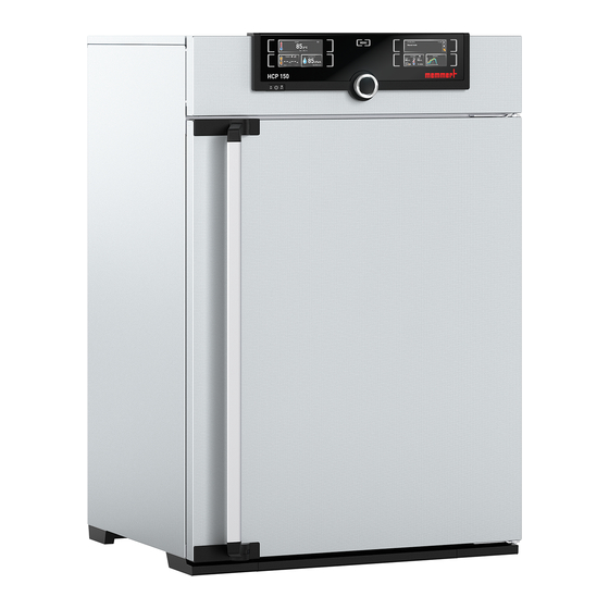
Page 10: Construction And Description
Construction and description Construction and description 2.1 Design Fig. 2 Design of HCP humidity chambers 1 ControlCOCKPIT with capacitive function 4 Stainless steel perforated sheet keys and LCD displays (see page 25) 5 Inner glass door 2 On/Off switch (see page 22) 6 Nameplate (see page 13) 3 Chamber fan 2.2 Description and function... -
Page 11: Working Range
Construction and description 2.3 Working range The temperature-humidity diagram (Fig. 3) specifies at what range of temperature and humi- dity a permanent operation is possible. NOTICE If in operation for long periods at the upper level or outside the working range, puddles of water may form inside the chamber and water may force its way out of the door seal. -
Page 12: Material
Construction and description 2.4 Material For the outer housing, MEMMERT uses stainless steel (Mat.No. 1.4016 – ASTM 430) and for the interior, stainless steel (Mat.No. 1.4301 – ASTM 304) is used, which stands out through its high stability, optimal hygienic properties and corrosion resistance to many (but not all!) chemical compounds (caution for example with chlorine compounds). -
Page 13: Designation (Nameplate)
Construction and description Ethernet interface Via Ethernet interface, the appliance can be connected to a network, so that you can trans- fer programs created with the AtmoCONTROL software to the appliance and read out proto- cols. The Ethernet interface is located on the rear of the appliance (Fig. -
Page 14: Technical Data
Construction and description 2.8 Technical data Appliance size Appliance width D* [mm] Appliance height E* [mm] 1071 1181 (varies due to adjustable feet) Appliance depth F* (without door handle) [mm] Depth of door handle [mm] Chamber width A* [mm] Chamber height B* [mm] Interior depth C* [mm] (less 35 mm for fan) Chamber volume [litres] Net weight [kg]... -
Page 15: Applied Directives And Standards
DIN EN 61 010-1 (VDE 0411 part 1) DIN EN 61 010-2-010 (VDE 0411 part 2-010) EN 61 010-1:2001, EN 61 010-2-010 2.10 Declaration of conformity You can download the EC declaration of conformity of the appliance online: English: http://www.memmert.com/en/service/downloads/ce-statement/ German: http://www.memmert.com/de/service/downloads/eg-konformitaetserklaerung/ D39303 | Date 09/2018... -
Page 16: Ambient Conditions
Construction and description 2.11 Ambient conditions ► The appliance may only be used in enclosed areas and under the following ambient condi- tions: Ambient temperature 10 °C to 35 °C Humidity rh max. 70 % non-condensing Overvoltage category Pollution degree Altitude of installation max. -
Page 17: Delivery, Transport And Setting Up
Delivery, transport and setting up Delivery, transport and setting up 3.1 For your safety WARNING Because of the heavy weight of the appliance, you could injure yourself if you try to lift it. At least two people are needed to carry ICO 50 appliances, or four people for ICO 105 and ICO 150 appli- ances. -
Page 18: Delivery
Delivery, transport and setting up 3.2 Delivery The appliance is packed in cardboard and is delivered on a wooden palette. 3.3 Transport The appliance can be transported in the following ways: ► With a forklift truck; move the forks of the truck entirely under the pallet. ►... -
Page 19: Setting Up
Delivery, transport and setting up 3.6 Setting up 3.6.1 Preconditions The installation site must be flat and horizontal and must be able to reliably bear the weight of the appliance (see Technical data on page 14). Do not place the appliance on a flamma- ble surface. - Page 20 Always attach the appliance to a wall with the tilt protection included in the delivery. In case there is not enough space, do not put the appliance into operation and do not open the door. Contact the Memmert service (see page 2). 1. Screw the tilt protection onto the back of the ap- pliance as illustrated.
-
Page 21: Putting Into Operation
Putting into operation Putting into operation NOTICE When putting the appliance into operation for the first time, do not leave it unattended until it has reached a steady state. 4.1 Connect the appliance to the power supply WARNING Condensation in the electrical components may cause short circuits. After transporting or storing the device under humid conditions, re- move it from its packaging and let it ventilate for at least 24 hours in normal environmental conditions. -
Page 22: Switching On
Putting into operation 4.2.2 Filling and connecting the water tank Fill the supplied water tank with water and use the enclosed tube to connect it to the “H O” connection on the rear of the chamber (Fig. 11). 4.3 Switching on Switch on the appliance by pressing the main switch on the front of the appliance ( Fig. -
Page 23: Operation And Control
Operation and control Operation and control 5.1 For your safety WARNING Leaving the door open during operation can cause the appliance to overheat or pose a fi re hazard. Do not leave the door open during operation. WARNING Hot steam can build up inside the appliance. You could be scalded on opening the door. -
Page 24: Loading The Appliance
Operation and control 5.4 Loading the appliance WARNING When loading the appliance with an unsuitable load, poisonous or explosive vapours or gases may be produced. This could cause the appliance to explode, and people could be severely injured or poi- soned. - Page 25 Operation and control TEMP TEMP Fr 20.10.2010 20:31 LIGHT LIGHT 12.09.2012 13:44 Manual mode Holz trocknen °C °C aufheizen 09:12h Set 37.0 °C °C TIMER HUMIDITY ALARM of °C GRAPH TIMER ALARM °C 000°C .5 °C .5 °C auto 000°C auto off Ende 13:30 23.11.
- Page 26 Operation and control 3. Save the set value by pressing the confir- TEMP mation key. The display returns to normal and the appliance begins adjusting to the .2 °C defined set value. Set 37 .0 °C Additional parameters can be set accordingly. If no new values are entered or confirmed for approx.
- Page 27 Operation and control 5.5.4 Manual mode In this operating mode, the appliance runs in permanent operation at the values set on the ControlCOCKPIT. Adjustment options As described in chapter 5.5.2 , you can set the following parameters after pressing the cor- responding activation key (in any sequence): Temperature TEMP...
- Page 28 Operation and control The display now shows the remaining time TIMER in a large font and the approximate end time 12.09.2012 13:44 Timer active in a smaller font beneath. The status display Timer active shows 13:30 23.11. 4. Now, as described under 5.5.2, set the individual values which you want the appliance to operate at.
- Page 29 Operation and control Only the program currently selected in menu mode and shown in the display can be used. If you want to process another program, you need to activate it in menu mode first (see description starting on page 51). 3.
-
Page 30: Monitoring Function
Operation and control You can now ► restart the program as described ► select another program to run in menu mode (see page 51) and run it as described. ► return to manual mode. To do so, reactivate it by 12.09.2012 13:44 pressing the activation key next to the status display,... - Page 31 Operation and control Emergency operation °C Setting MAX temperature Controller error Fig. 17 Schematic diagram of how TWW temperature monitoring works Automatic temperature monitor ( ASF) ASF is a monitoring device that automatically follows the set temperature setpoint within an adjustable tolerance band (Fig.
- Page 32 Operation and control Mechanical temperature monitoring: Temperature limiter (TB) The appliance is equipped with a mechanical temperature limiter TEMP (TB) of protection class 1 in accordance with DIN 12 880. If the electronic monitoring unit fails during operation and the default °C maximum temperature is exceeded by at least 20 °C, the tempera- ture limiter, as the final protective measure, switches off the...
- Page 33 Operation and control 5. With the turn control, select ON ( ) or ALARM OFF (). .5 °C .5 °C auto 6. Press the confirmation key to confirm. ALARM The ASF tolerance band setting is acti- vated. °C .5 °C auto 7.
- Page 34 Operation and control 2. Turn the turn control until the humidity ALARM monitoring entry is highlighted. .0 %rh .0 %rh 3. Accept the selection by pressing the con- ALARM firmation key. The lower humidity alarm limit is automatically highlighted. .0 %rh 4.
-
Page 35: Graph
Operation and control 5.7 Graph The GRAPH display provides an overview of the chronological sequence of the setpoint values and actual values for temperature and humidity content as a curve. Press the activation key to the °C 12.09.2012 Fr 20.10.2010 20:34 GRAPH right of the display. -
Page 36: Ending Operation
Operation and control 5.8 Ending operation WARNING Hot steam can build up inside the appliance. You could be scalded on opening the door. Allow the appliance to cool before opening the door. WARNING Depending on operation, the surfaces in the interior of the appliance and the chamber load may still be very hot after the appliance is switched off. -
Page 37: Malfunctions, Warning And Error Messages
After removing covers, live parts may be exposed. Touching these can lead to an electrical shock. Do not try to rectify appliance er- rors yourself by opening the appliance, but contact the MEMMERT customer service department (see page 2) or an authorised service point. -
Page 38: Malfunctions, Operating Problems And Appliance Errors
Malfunctions, warning and error messages 6.1.2 Humidity monitoring (only for appliances in the corresponding confi guration) Description Cause Action Water tank Fill the water tank with deminer- Page Error display symbol empty alised/distilled water and press the confirmation key HUMIDITY Set 55 .0 %rh MaxAl... - Page 39 Contact customer Page 2 The system files could service white not be loaded ► Orange : The fonts and images could Download the firm- not be loaded ware update from memmert.com and install it D39303 | Date 09/2018...
-
Page 40: Power Failure
Malfunctions, warning and error messages 6.3 Power failure In case of a power failure, the appliance operates as follows: In manual mode After power supply has been restored, operation is continued with the parameters set. The time and duration of the power failure are documented in the log memory. In timer or program mode In case of an interruption of the power supply of less than 60 minutes, the current program is continued from the point at which it was interrupted. -
Page 41: Menu Mode
Menu mode Menu mode In menu mode, you can make basic settings, load programs and export protocols, as well as calibrate the appliance. Caution: Before changing menu settings, read the description of the respective functions on the fol- lowing pages to avoid possible damage to the appliance and/or chamber load. To enter menu mode, press the MENU key. -
Page 42: Basic Operation In Menu Mode Using The Example Of Language Selection
Menu mode 7.2 Basic operation in menu mode using the example of language selection In general, all settings in menu mode are done just like in operating mode: Activate the respective display, use the turn control for setting and press the confirmation key to accept the change. -
Page 43: Setup
Menu mode All other settings can be made accordingly. The settings possible are described in the follow- ing sections. If no new values are entered or confirmed for approx. 30 seconds, the appliance automati- cally restores the former values. 7.3 Setup 7.3.1 Overview SETUP In the... - Page 44 Menu mode SETUP 1. Activate the display. The entry SETUP SETUP address is automatically highlighted. IP address 192. 168. 1 0 0 . 100 Balance Subnet mask 255. 255. 0 . 0 IP Adresse 192. 168. 1 0 0 . 100 Unit Einheit °C...
-
Page 45: Date And Time
Menu mode Timer Timer Fig. 23 Timer mode Timer independent of setpoint: Timer starts immediately after activation Timer setpoint-dependent: Timer does not start until tolerance band is reached 7.3.5 Remote control (AtmoREMOTE) In the setup entry remote control, you can set whether the appliance should be controlled via remote control and if so, in which mode. - Page 46 Menu mode 1. Activate the time setting. To do so, press the activation key on the right side of Date and time TIME display. The display is enlarged Date 2012 Date and the first adjustment option ( Time 12 : 00 automatically highlighted.
-
Page 47: Calibration
Menu mode 8. Now, set date (day, month year) and time (hours, minutes) in the same way. Accept Date 2012 the selection by pressing the confirma- Time 12 : 00 tion key. Time zone GMT 00:00 Daylight savings 7.5 Calibration NOTICE To guarantee perfect control, we recommend to calibrate the appliance once a year. - Page 48 Menu mode 1. Press the activation key to the right of the JUSTIEREN Calibration CALIB display. The display is enlarged Temperatur Cal1 40.0 -0,2 Temperature 30.0 °C and the temperature adjustment option Cal1 Cal2 100.0 +0,1 40.0 Humidity °C Cal2 is automatically selected.
- Page 49 Menu mode 9. In the SETUP, adjust the calibration value Cal2 to +1.6 K (reference value measured 30.0 Cal1 minus value displayed) and save the set- 42.0 Cal2 ting by pressing the confirmation key. 60.0 Cal3 10. After the calibration procedure, the TEMP temperature measured by the reference instrument should now also be 42 °C.
- Page 50 Menu mode Humidity 2. Turn the turn control until highlighted. Temperature 40.0 Cal1 Humidity 50.0 Cal2 80.0 Cal3 3. Press the confirmation key repeatedly, until the calibration point Cal2 is selected. Temperature 40.0 Cal1 Humidity 50.0 Cal2 80.0 Cal3 4. With the turn control, set the calibration point Cal2 to 60% rh.
-
Page 51: Program
Menu mode 10. In the SETUP, adjust the compensation correction value Cal2 to -1.5% (actual Temperature 40.0 Cal1 value measured minus setpoint humid- Humidity 60.0 -1.5 Cal2 ity) and save the setting by pressing the 80.0 Cal3 confirmation key. 11. After the calibration procedure, the hu- midity measured by the reference instru- HUMIDITY ment should now also be 60% rh. -
Page 52: Sounds
Menu mode 4. Accept the selection by pressing the confirmation key. The program is now Select Test 012 Delete Test 022 loaded, which is indicated by the transfer Test 013 symbol. Test 014 Test 023 Test 015 5. As soon as the program is ready, the Select Test 012 Select. -
Page 53: Protocol
Menu mode 3. With the turn control, select the desired Sound setting – in this example OFF (). Keysound At the end On alarm If door open 4. Save the setting by pressing the confir- Sound mation key. Keysound If an acoustic alarm sounds, it can be At the end turned off by pressing the confirmation On alarm... -
Page 54: User Id
Menu mode For a description of how to import and process protocol data in AtmoCONTROL or read it out via Ethernet, please refer to the separate AtmoCONTROL manual. 7.9 USER ID 7.9.1 Description With the USER ID function, you can lock the settings of individual (e.g. temperature) or all parameters, so that they cannot be changed at the appliance by accident or unauthorised persons. -
Page 55: Maintenance And Servicing
Maintenance and Servicing Maintenance and Servicing WARNING Danger due to electric shock. Disconnect the mains plug before any cleaning or maintenance work. 8.1 Regular maintenance Annually: ► Check the sterile filter in the control unit and the water pump filter in the rear panel and replace them if they are dirty. -
Page 56: Storage And Disposal
Storage and disposal Storage and disposal 9.1 Storage The appliance may only be stored under the following conditions: ► in a dry and enclosed, dust-free room ► frost-free ► disconnected from the power supply and water supply Disconnect the tube of the water supply tank and empty it. 9.2 Disposal This product is subject to the Directive 2002/96/EC on Waste Electrical and Electronic Equipment (WEEE) of the European Parliament and of... -
Page 57: Index
Index Index End of programme 29 Error message 39 Accessories 16 Operating modes 26 Error messages 37 Activation button 25 Operating personnel 8 Ethernet 13 Alarm 30, 31, 33, 37 Operating problems 38 Ambient conditions 16 Operation 23 Ambient temperature 16 Forklift truck 18 Appliance error 38 Packaging material 18... - Page 58 Index Temperature monitoring 30 Temperature sensor 30 Tilt protection 20 Time 45 Timer 27 Timer mode 44 Transport 17, 18 Transport damage 18 Turn control 25 TWW 30 TWW temperature monitor- ing 31 Type plate 13 Unit 44 Unpacking 18 USB port 12, 53 USER ID 54 Warning messages 12, 37...
- Page 60 Humidity chamber HCP D39303 | Date 09/2018 English Memmert GmbH + Co. KG Willi-Memmert-Straße 90-96 | D-91186 Büchenbach Tel. +49 9122 925-0 | Fax +49 9122 14585 E-Mail: sales@memmert.com facebook.com/memmert.family Die Experten-Plattform: www.atmosafe.net...
Need help?
Do you have a question about the HCP105 and is the answer not in the manual?
Questions and answers