
Related Manuals for Memmert HPP Series


Summary of Contents for Memmert HPP Series
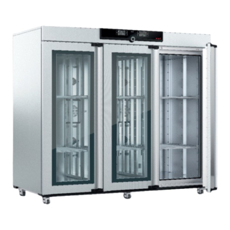
- Page 1 OPERATING INSTRUCTIONS CONSTANT CLIMATE CHAMBER HPP 1400/2200 MADE IN GERMANY. www.memmert.com...
- Page 2 Please contact our customer service before sending appliances for repair or before returning equipment, otherwise, we have to refuse acceptance of the shipment. © 2019 MEMMERT GmbH + Co. KG D33464 | Date 12/2019 We reserve the right to make changes...
- Page 3 Function and operation are identical. Other documents that have to be observed: ► For operation of the appliance with MEMMERT AtmoCONTROL, observe the separate software manual. To open the AtmoCONTROL software manual, click on “Help” in the AtmoCONTROL menu bar.
-
Page 4: Table Of Contents
Contents Contents For your Safety Terms and signs used......................6 Product safety and dangers ....................7 Requirements of the operating personnel ................7 Responsibility of the owner ....................7 Intended use ........................8 Changes and alterations ...................... 8 Behaviour in case of malfunctions and irregularities ............8 Switching off the appliance in an emergency .............. - Page 5 Contents Malfunctions, warning and error messages Warning messages of the monitoring function ..............37 Malfunctions, operating problems and appliance errors ..........38 Power failure ........................40 Menu mode Overview ..........................41 Basic operation in menu mode using the example of language selection ....... 42 Setup..........................
-
Page 6: For Your Safety
For your Safety For your Safety 1.1 Terms and signs used In this manual and on the appliance itself, certain common terms and signs are used to warn you of possible dangers or to give you hints that are important in avoiding injury or damage. Observe and follow these hints and regulations to avoid accidents and damage. -
Page 7: Product Safety And Dangers
For your Safety 1.2 Product safety and dangers The appliances described in this manual are technically sophisticated, manufactured using high-quality materials and subject to many hours of testing in the factory. They contain the latest technology and comply with recognised technical safety regulations. However, there are still risks involved, even when the appliances are used as intended. -
Page 8: Intended Use
For your Safety ► is responsible for ensuring that unauthorised persons have no access to the appliance; ► is responsible for ensuring that the maintenance plan is adhered to and that maintenance work is carried out properly (see page 58); ►... -
Page 9: Construction And Description
Construction and description Construction and description 2.1 Construction Fig. 2 Construction 1 ControlCOCKPIT with capacitive function 6 Lockable castors with extendable feet keys and LCD displays (see page 25) (see page18) 2 On/Off switch (see page 22) 7 Nameplate (see page 12) 3 Door handle (see page 23) 8 Door handle (see page 23) 4 Slide-in units... -
Page 10: Description
Peltier module. 2.3 Material For the outer housing, MEMMERT uses stainless steel (Mat.No. 1.4016 – ASTM 430) and for the interior, stainless steel (Mat.No. 1.4301 – ASTM 304) is used, which stands out through its high stability, optimal hygienic properties and corrosion resistance to many (but not all!) chemical compounds (caution for example with chlorine compounds). - Page 11 Construction and description 2.5.2 Communication interfaces The interfaces are intended for appliances which meet the requirements of IEC 60950-1. USB interface The appliance is fitted by default with a USB interface in accordance with the USB specifi- cation. This way, you can ►...
-
Page 12: Designation (Nameplate)
Construction and description 2.6 Designation ( nameplate) The nameplate (Fig. 5) provides information about the appliance model, manufacturer and technical data. It is attached to the front of the appliance on the right, behind the right door (see page 9). Typ: HPP1400 F-Nr.: WA18.3008 230 V~ 50/60 Hz... -
Page 13: Technical Data
Construction and description 2.7 Technical data Appliance size 1400 2200 Appliance width D [mm] 1435 2157 Appliance height E (incl. castors) [mm] 1905 1905 Appliance depth F [mm] 1005 1005 Depth of door lock [mm] Chamber width A [mm] 1250 1972 Chamber height B [mm]... -
Page 14: Applied Directives And Standards
2.8 Applied directives and standards Based on the standards and guidelines listed in the following, the products described in this manual have received a CE label from the company Memmert: ► Directive 2004/108/EC amended (Directive of the council for harmonisation of the laws of the member states on electromagnetic compatibility). -
Page 15: Ambient Conditions
Construction and description 2.10 Ambient conditions ► The appliance may only be used in enclosed areas and under the following ambient condi- tions: Ambient temperature 16 ºC to 40 ºC Humidity rh max. 70 % non-condensing Overvoltage category Pollution degree Altitude of installation max. -
Page 16: Delivery, Transport And Setting Up
Delivery, transport and setting up Delivery, transport and setting up 3.1 Safety regulations Warning! Because of the heavy weight of the appliance, you could injure yourself if you try to lift it. The appliance may only be transported by a manual pallet jack or forklift truck. -
Page 17: Storage After Delivery
(see page 19). If there is not enough space, do not begin operating the appliance and do not open the doors. Contact the Memmert service (see page 2). 3.6.1 Preconditions The appliance may only be installed on the bottom. The installation site must be flat and horizontal and must be able to reliably bear the weight of the appliance (see Technical data on page 13). - Page 18 Delivery, transport and setting up 3.6.2 Level and secure the device against rolling away The height of the appliance can be adjusted using the heavy-duty castors attached to the bot- tom of the appliance. It can also be secured against rolling away or being shifted. To do this, the feet must be extended.
- Page 19 Delivery, transport and setting up 3.6.3 Tilt protection Attach the appliance to a wall with the tilt protection. The tilt protection is included in the delivery. 3. Screw the tilt protection onto the back of the ap- pliance as illustrated. 4.
- Page 20 Delivery, transport and setting up 3.6.4 Adjusting the doors You can adjust the doors if necessary, for example if they are warped due to uneven flooring. There are two adjusting screws each at the top and the bottom of each door for this purpose (Fig.
-
Page 21: Putting Into Operation
4.2 Filling and connecting the water tank Water specifications Only demineralised/deionised water with the following specifications may be used in Memmert appliances: ► Conductivity of 5 – 10 μS/cm ► pH value between 5 and 7 ►... -
Page 22: Switching On
Putting into operation 4.3 Switching on Switch on the appliance by pressing the main switch on the front of the appliance ( Fig. 16 ). The start-up process is shown by three animated white dots . If the dots have another colour, an error has occurred (see page 39). -
Page 23: Operation And Control
Operation and control Operation and control 5.1 Operating personnel The appliance may only be operated by persons who are of legal age and have been instruct- ed accordingly. Personnel who are to be trained, instructed or who are undergoing general training may only work with the appliance under the continuous supervision of an experi- enced person. -
Page 24: Loading The Appliance
Operation and control 5.3 Loading the appliance Warning! When loading the appliance with an unsuitable load, poisonous or explosive vapours or gases may be produced. This could cause the appliance to explode, and people could be severely injured or poi- soned. -
Page 25: Operating The Appliance
Operation and control 5.4 Operating the appliance 5.4.1 ControlCOCKPIT In manual operation, the desired parameters are entered at the ControlCOCKPIT on the front of the appliance (Fig. 20 ). You can also make basic settings here (menu mode). Additionally, warning messages are displayed, e.g. if the temperature is exceeded. In programme mode, the parameters defined, the programme description, the programme segment currently active and programme duration remaining are displayed (for a more detailed description, see page 29). - Page 26 Operation and control 5.4.2 Basic operation In general, all settings are made according to the following pattern: 1. Activate the desired parameter TEMP TEMP (e.g. temperature). To do so, press the .4 °C corresponding activation key on the left °C .5°C or right or the respective display.
- Page 27 Operation and control The status display shows you which operating mode or operating state the appliance is currently in. The current operating state is highlighted in colour and indicated by the text display: Appliance is in programme mode 12.09.2012 13:44 ■...
- Page 28 Operation and control A high level of air humidity in the interior can only be achieved without condensation if the interior is thoroughly heated. For this reason, how fast the humidity is dynamically adjusted to approach the setpoint depends on the interior temperature. 5.4.5 Operation with digital backwards counter with target time setting, adjustable from 1 minute to 99 days (timer) In timer operation, you can adjust the time the appliance runs at the set values.
- Page 29 Operation and control To deactivate the timer, open the timer display by pressing the TIMER activation key again and then turning the turn control to reduce the timer setting until --:-- is displayed. Confirm with the confirmation key. 9:00 23.11. 5.4.6 Programme mode In this operating mode, programmes saved in the appliance can be started with different combinations of individual parameters (temperature, fan speed, humidity) at staggered...
- Page 30 Operation and control You cannot change any parameters (e.g. the temperature) at the appliance while a ALARM GRAPH programme is running. However, the displays can still be used. Cancel programme You can cancel an active LIGHT LIGHT Fr 20.10.2010 20:31 12.11.2012 13:44 programme at any time.
-
Page 31: Monitoring Function
Operation and control You can now ► restart the programme as described ► select another programme for processing in menu mode (see page 54) and run it as described. ► return to manual mode. To do 12.09.2012 13:44 so, reactivate it by pressing the activation key next to the Manual mode status display, then turn the... - Page 32 Operation and control TWW takes overtemperature control and begins to regulate the monitoring temperature (Fig. 22). Emergency operation °C Setting MAX Set temperature Controller error Fig. 22 Schematic diagram of how TWW temperature monitoring works Automatic temperature monitor ( ASF) ASF is a monitoring device that automatically follows the set temperature setpoint within an adjustable tolerance band (Fig.
- Page 33 Operation and control Adjusting temperature monitoring Press the activation key to the left of the ALARM display. The temperature monitoring ALARM ALARM setting is automatically activated ( ). 000°C .0 °C .0 °C auto 000°C auto off Save the selection by pressing the confirma- ALARM tion key.
- Page 34 Operation and control 6. Press the confirmation key to confirm. ALARM The ASF tolerance band setting is acti- vated. °C .5 °C auto 7. With the turn control, adjust the desired ALARM tolerance band, e.g. 2.0 K. We recommend a tolerance band of 1 to °C .5 °C 3 K.
-
Page 35: Graph
Operation and control 3. Accept the selection by pressing the con- ALARM firmation key. The lower humidity alarm limit is automatically highlighted. .0 %rh 4. By turning the turn control, adjust the ALARM desired lower alarm limit, in the example on the right 50 % rh. -
Page 36: Ending Operation
Operation and control ► To change the time frame to °C 12.09.2012 Fr 20.10.2010 20: be displayed: Press the activa- tion key next to the ar- row symbols. The time frame to be displayed can now be 12 16 20 24 14.00 16.00 18.00... -
Page 37: Malfunctions, Warning And Error Messages
Ob- serve the separate service manual for this. Do not try to rectify appliance errors yourself but contact the MEMMERT customer service department (see page 2) or an authorised service point. -
Page 38: Malfunctions, Operating Problems And Appliance Errors
Malfunctions, warning and error messages 6.1.2 Humidity monitoring Description Cause Action Water tank Fill the water tank with water page Error symbol empty and press the confirmation key. HUMIDITY Set 55 .0 %rh MaxAl Upper humidity Open the door for 30 sec. and Alarm display ( limit exceeded wait to see if the appliance reliab-... - Page 39 Malfunctions, warning and error messages Error description Cause of error Rectifying errors ► Display T:E-3 in the Temperature operating The appliance can temperature display sensor defective. The moni- be temporarily toring sensor takes over the operated TEMP measurement function. ► Contact customer service as soon as °C...
-
Page 40: Power Failure
Malfunctions, warning and error messages 6.3 Power failure In case of a power failure, the appliance operates as follows: In manual mode After power supply has been restored, operation is continued with the parameters set. The time and duration of the power failure are documented in the log memory. In timer or programme mode In case of an interruption of the power supply of less than 60 minutes, the current pro- gramme is continued from the point at which it was interrupted. -
Page 41: Menu Mode
Menu mode Menu mode In menu mode, you can make basic settings, load programmes and export protocols, as well as adjust appliance parameters. Caution: Before changing menu settings, read the description of the respective functions on the fol- lowing pages to avoid possible damage to the appliance and/or chamber load. To enter menu mode, press the MENU key. -
Page 42: Basic Operation In Menu Mode Using The Example Of Language Selection
Menu mode 7.2 Basic operation in menu mode using the example of language selection In general, all settings in menu mode are done just like in manual mode: Activate the re- spective display, use the turn control for setting and press the confirmation key to accept the change. -
Page 43: Setup
Menu mode All other settings can be made accordingly. The settings possible are described in the follow- ing sections. If no new values are entered or confirmed for approx. 30 seconds, the appliance automati- cally returns to the main menu and restores the former values. 7.3 Setup 7.3.1 Overview SETUP... - Page 44 Menu mode SETUP 1. Activate the display. The entry SETUP SETUP address is automatically highlighted. IP address 192. 168. 1 0 0 . 100 Balance Subnet mask 255. 255. 0 . 0 IP Adresse 192. 168. 1 0 0 . 100 Unit °C Einheit...
- Page 45 Menu mode 7.3.4 Timer mode Here, you can choose whether the digital backwards counter with target time setting (see page 28) should run setpoint-de- IP address 255. 145. 1 3 6 . 225 pendent or not. This determines whether the timer should not Subnet mask 255.
- Page 46 Menu mode 7.3.6 Balance The distribution of the heating/cooling power (balance) between the upper and lower Peltier elements can be corrected depending on the specific application. The adjustment range is from -50 % to +50 %. upper heating/cooling power upper heating/cooling power lower heating/cooling power lower heating/cooling power +30%...
- Page 47 Menu mode Example: 1. Interval begins – dehumidification peltier modules cool at full power and generate coldest point (-12°C), depending on the set time interval. 2. Interval duration expired – dehumidification peltier modules are not operated for a short time, resulting in a local rise in temperature. The ice thaws and the melt water is chan- nelled out.
-
Page 48: Date And Time
Menu mode 7.4 Date and Time Time In the display, you can set date and time, time zone and daylight saving time. Changes can only be made in manual operating mode. Always set the time zone (and summer time yes/no) before you set the date and time. Avoid changing the set time after that since this can lead to gaps or overlapping when recording measured values. -
Page 49: Calibration
Menu mode 7. Set daylight savings to off () or on ) with the turn control – in this case Date 12 . 05 . 2012 on ( ). Save the setting by pressing the Time 12 : 00 confirmation key. - Page 50 Menu mode Example: Temperature deviation at 30 °C should be corrected. 1. Press the activation key to the right of JUSTIEREN Calibration CALIB display. The display is enlarged Temperatur Cal1 40.0 -0,2 Temperature °C and the temperature adjustment option Cal1 Cal2 100.0 +0,1...
- Page 51 Menu mode 9. In the SETUP, adjust the calibration value Cal2 to +1.6 K (actual value measured Cal1 minus setpoint temperature) and save the 30.0 Cal2 setting by pressing the confirmation key. 40.0 Cal3 10. After the calibration procedure, the temperature measured by the reference TEMP instrument should now also be 30 °C.
- Page 52 Menu mode Example: Humidity deviation at 90 % should be corrected. 1. Press the activation key to the right of JUSTIEREN Calibration CALIB display. The display is enlarged Temperatur Cal1 40.0 -0,2 Temperature °C and the temperature adjustment option Cal1 Cal2 100.0 +0,1...
- Page 53 Menu mode 9. Wait until the appliance reaches the set humidity and displays 60 % rh. The HUMIDITY reference instrument for example displays 58.5 % rh. .0 %rh 78.5 %rh Set 80 .0 %rh 10. In the SETUP, adjust the calibration value Cal2 to -1.5 % (actual value measured Temperature 10.0...
-
Page 54: Program
Menu mode 7.6 Program PROG In the display, programmes created using the AtmoCONTROL software can be trans- ferred to the appliance and saved on a USB storage medium. Here, programme to be used in manual mode can also be selected (see page 29) and programmes can be deleted. To load a programme from a USB stor- age medium: Connect the USB storage medium with the saved programme(s) -
Page 55: Sound
Menu mode 7.7 Sound Sound In the display, it can be define whether or not the appliance should emit acoustic signals and, if yes, on which events: ► on the press of a key ► at the end of a programme ►... -
Page 56: Protocol
Menu mode 7.8 Protocol The appliance continually logs all relevant measured values, settings and error messages at 1-minute intervals. The internal log memory is of the continuous memory type. The logging function cannot be switched off and is always active. The measured data are stored in the appliance, safe from manipulation. -
Page 57: User-Id
Menu mode 7.9 User-ID 7.9.1 Description With the User-ID function, you can lock the settings of individual (e.g. temperature) or all parameters, so that they cannot be changed at the appliance by accident or unauthorised persons. You can also lock setting options in menu mode (e.g. adjustment or date and time settings) this way. -
Page 58: Maintenance And Service
Maintenance and service Maintenance and service 8.1 Cleaning Warning! Danger due to electric shock. Before doing any maintenance work, pull out the mains plug. Warning! In case of appliances of a certain size, you can get accidentally locked in, which is life-threatening. Do not climb into the appliance! Caution! Danger of cuts due to sharp edges. -
Page 59: Regular Maintenance
Maintenance and service 8.2 Regular maintenance Once a year, grease the moving parts of the doors (hinges and lock) with thin silicone grease and check that the hinge screws are not loose. To guarantee perfect control, we recommend to calibrate the appliance once a year (see page 49). -
Page 60: Storage And Disposal
Storage and disposal Storage and disposal 9.1 Storage The appliance may only be stored under the following conditions: ► in a dry and enclosed, dust-free room ► frost-free ► disconnected from the power supply Before storage, remove water tube and empty the water tank (see page 21). 9.2 Disposal This product is subject to the Directive 2012/19/EC on Waste Electrical and Electronic Equipment (WEEE) of the European Parliament... -
Page 61: Index
Index Index Menu 41, 47 Minimum clearances 17 Accessories 15 Electrical connection 10 Monitoring function 31 Acoustic signals 48 Electrical equipment 10 Monitoring temperature 31 Activation button 26 Electronic temperature moni- Adjusting doors 20 toring 31 Adjustment , 18 Emergency 8 Nameplate 12 Alarm 31, 32, 34, 37 Ending operation 36... - Page 62 Index Switching off 36 Switching on 22 Unit 44 Unpacking 16 USB interface 11, 55 Technical data 13 User ID 56 Temperature 27 Temperature adjustment 48 Temperature comparison 48 Warning messages 11, 37 Temperature deviation 49 Water specifications 21 Temperature monitor 31, 32 Water tank 21 Temperature monitoring 30, Weight 13...
- Page 64 Constant Climate Chamber HPP 1400/2200 D33464 | Date 12/2019 englisch Memmert GmbH + Co. KG Postfach 1720 | D-91107 Schwabach Tel. +49 9122 925-0 | Fax +49 9122 14585 E-Mail: sales@memmert.com facebook.com/memmert.family...
Need help?
Do you have a question about the HPP Series and is the answer not in the manual?
Questions and answers