
Related Manuals for Planet IPOE-171-60W


Summary of Contents for Planet IPOE-171-60W
- Page 1 Industrial Single-Port 10/100/1000Mbps 802.3bt PoE Injector IPOE-171 Series User’s Manual...
- Page 2 PLANET has made every effort to ensure that this User’s Manual is accurate; PLANET disclaims liability for any inaccuracies or omissions that may have occurred. Information in this User’s Manual is subject to change without notice and does not represent a commitment on the part of PLANET.
- Page 3 Do not dispose of WEEE as unsorted municipal waste and have to collect such WEEE separately. Revision PLANET IPOE-171 Series User’s Manual MODEL: IPOE-171-60W, IPOE-171-95W REVISION: 1.0 (April, 2018) Part No.: 2350-AF0510-000...
-
Page 4: Table Of Contents
5.2 Removing Device from DIN Rail ...........18 5.3 Wall-mount Plate Mounting ..........19 6. Hardware Installation ..............20 6.1 Before Installation ...............20 6.2 IPOE-171-60W Installation ...........20 6.3 IPOE-171-60W and IPOE-171S Installation ......22 6.4 IPOE-171-60W and IPOE-E172 Installation ......23 7. Customer Support ..............25... -
Page 5: Introduction
1. Introduction Thank you for purchasing PLANET IPOE-171 Single-port 10/100/1000Mbps series injector. Model LAN Port Speed PoE Standard PoE Budget IPOE-171-60W 10/100/1000Mbps IEEE 802.3af/at/bt 60 watts IPOE-171-95W 10/100/1000Mbps IEEE 802.3af/at/bt 95 watts Please unpack the box of the device carefully, and the box should contain the following items: 802.3bt PoE injector x 1... -
Page 6: Product Features
¾ 1-port Data + Power output ¾ 1-port Data input ‹ 1 terminal block for master and slave power input ¾ IPOE-171-60W Power Range: 48 ~ 56V DC redundant power ¾ IPOE-171-95W Power Range: 24 ~ 48V DC redundant power „ Power over Ethernet ‹... - Page 7 ‹ IEEE 802.3ab 1000BASE-T ‹ IEEE 802.3bt 4-pair Power over Ethernet ‹ IEEE 802.3at Power over Ethernet Plus ‹ IEEE 802.3af Power over Ethernet ‹ FCC Part 15 Class A, CE PSE (Power Sourcing Equipment) is a device (switch, or hub for instance) that provides power in a PoE setup. Maximum allowed continuous output power per such device in IEEE 802.3af is 15.4W, in IEEE 802.3at is 30W, and in IEEE 802.3bt is 60~95W.
-
Page 8: Product Specifications
3. Product Specifications Product IPOE-171-60W IPOE-171-95W Hardware Specifications 1 x RJ45 STP Input Port Data In 1 x RJ45 STP Interface Output Port PoE (Data + Power) Out Input Power Terminal Block Twisted-pair cable up to 100 meters (328ft) 10BASE-T: 4-pair UTP Cat. 3, 4, 5, 5e, 6 Network Cable* 100BASE-TX: 4-pair UTP Cat. - Page 9 DC 50~54V / DC 54V / 95-watt 60-watt PoE via PoE via 4-pair PoE Power Output 4-pair Budget DC 48~49V / DC 54V / 30-watt 30-watt PoE via PoE via 2-pair 2-pair Max. 60W@1 m Max. 89.5W@1 m PoE Power Output cable cable PoE Power Supply Type...
-
Page 10: Product Outlook
4. Product Outlook 4.1 Physical Dimensions (example on IPOE-171A-95W) Top View V1+ V1- V2+ V2- Input PWR1 Fault PWR2 DC 24~48V Front View Side View Rear View DIN-Rail Kit Mounting Kit Mounting Kit Dimensions ( unit = mm ) Figure 1: IPOE-171-95W dimensions... -
Page 11: Product Outlook
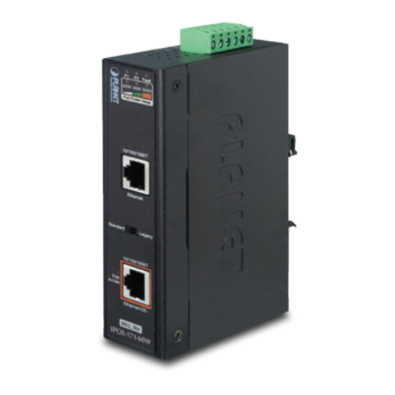
P2 Fault 20W 40W 60W+ 30W 60W 90W+ PoE Power Usage PoE Power Usage 10/100/1000T 10/100/1000T Ethernet Ethernet Standard Legacy Standard Legacy 10/100/1000T 10/100/1000T in-Use in-Use Ethernet+DC Ethernet+DC 802.3bt 802.3bt IPOE-171-60W IPOE-171-95W Figure 2: IPOE-171-60W outlook Figure 3: IPOE-171-95W outlook... - Page 12 „ IPOE-171-60W LED Indicators: Color Function Green Lights to indicate power 1 has power. Green Lights to indicate power 2 has power. Lights to indicate either power 1 or power 2 has FAULT no power. Lights to indicate the device is providing PoE PoE-in-Use Orange power.
- Page 13 „ IPOE-171-95W LED Indicators: Color Function Green Lights to indicate power 1 has power. Green Lights to indicate power 2 has power. Lights to indicate either power 1 or power 2 has FAULT no power. Lights to indicate the device is providing PoE PoE-in-Use Orange power.
-
Page 14: Industrial Poe+ Injector Upper Panel
DC power inputs. 1 2 3 4 5 6 V1+ V1- V2+ V2- Input PWR1 Fault PWR2 DC 48~56V Figure 4: IPOE-171-60W upper panel. 1 2 3 4 5 6 V1+ V1- V2+ V2- Input PWR1 Fault PWR2 DC 24~48V... -
Page 15: Wiring The Power Inputs
4.4 Wiring the Power Inputs The 6-contact terminal block connector on the top panel of the IPOE- 171 series is used for two DC redundant power inputs. Please follow the steps below to insert the power wire. Step 1: Insert Positive / Negative DC power wires into Contacts 1 and 2 for POWER 1, or 5 and 6 for POWER 2. -
Page 16: Wiring The Fault Alarm Contact
4.5 Wiring the Fault Alarm Contact The fault alarm contacts are in the middle of the terminal block connector as the picture shows below. After inserting the wires, the IPOE-171 series will detect the fault status of the power failure and then form an open circuit. -
Page 17: Mounting Installation
Please read the following sections and perform the procedures in the order being presented. In the installation steps below, this manual uses PLANET IGS-801 8-port Industrial Gigabit Switch as an example. The steps for PLANET Industrial Slim-type Switch, Indus-... -
Page 18: Removing Device From Din Rail
Step 2: The DIN-rail bracket should be tightly on the track. Figure 11: DIN-rail mount industrial device 5.2 Removing Device from DIN Rail Step 1: Please refer to following procedure to remove the industrial device from the track. Figure 12: Removing industrial device from DIN rail... -
Page 19: Wall-Mount Plate Mounting
Step 2: Slightly push the unit down and lightly pull its bottom out to completely remove it from the track. 5.3 Wall-mount Plate Mounting To install the industrial device on the wall, please follow the instructions described below. Step 1: Unscrew the DIN-rail bracket to be removed from the industrial device. -
Page 20: Hardware Installation
6.2 IPOE-171-60W Installation 1. Connect the power ranging from 48V DC to 56V DC to the 6-pin terminal block of the IPOE-171-60W. The power LED will be steadily 2. Connect a standard Ethernet cable from an Ethernet switch or PC workstation to “Ethernet”... - Page 21 1000BASE-T UTP with PoE Power Line (DC) Figure 14: Connecting architecture with IEEE 802.3af/at/bt device Once the IPOE-171-60W detects the existence of an IEEE 802.3af/at/bt device, the PoE-in-Use LED indicator will be steadily on to show it is providing power.
-
Page 22: Ipoe-171-60W And Ipoe-171S Installation
Output” of IPOE-171S to remote device. 2. Connect the power ranging from 48V DC to 56V DC to the 6-pin terminal block of the IPOE-171-60W. The power LED will be steadily 3. Connect a standard Ethernet cable from an Ethernet switch or PC workstation to the “Ethernet”... -
Page 23: Ipoe-171-60W And Ipoe-E172 Installation
6.4 IPOE-171-60W and IPOE-E172 Installation 1. Connect the power ranging from 48V DC to 56V DC to the 6-pin terminal block of the IPOE-171-60W. The power LED will be steadily 2. Connect a standard Ethernet cable from an Ethernet switch or PC workstation to the "Ethernet"... - Page 24 Industrial 802.3bt PoE PTZ PoE Extender IP Camera 1000BASE-T UTP 1000BASE-T UTP with PoE Power Line (DC) Figure 16: Connected Architecture of IPOE-171-60W and IPOE-E172 Depending on the length of cable, the PoE power which PD receives is different. Note...
-
Page 25: Customer Support
7. Customer Support Thank you for purchasing PLANET products. You can browse our online FAQ resource at the PLANET Web site first to check if it could solve your issue. If you need more support information, please contact PLANET PoE support team. - Page 26 IPOE-171-60W/IPOE-171-95W * Produced by: Manufacturer‘s Name : Planet Technology Corp. 10F., No.96, Minquan Rd., Xindian Dist., New Taipei City 231, Taiwan Manufacturer‘s Address: is herewith confirmed to comply with the requirements set out in the Council Directive on the Approximation of the Laws of the Member States relating to Electromagnetic Compatibility Directive on 2014/30/EU.
Need help?
Do you have a question about the IPOE-171-60W and is the answer not in the manual?
Questions and answers