
Related Manuals for Planet IPOE-171-60W


Summary of Contents for Planet IPOE-171-60W
- Page 1 Industrial 802.3bt Multi-Gigabit PoE++ Injector IPOE-171-60W/IPOE-171-95W User’s Manual...
-
Page 2: Table Of Contents
4. Mounting Installation ..............13 4.1 DIN-rail Mounting Installation ..........13 4.2 Wall-mount Plate Mounting ..........13 4.3 Side Wall-mount Plate Mounting ..........14 4.4 Grounding the Device ............14 5. Hardware Installation ..............15 5.1 Before Installation ..............15 5.2 IPOE-171-60W/IPOE-171-95W Installation ......15 6. Customer Support ..............17... -
Page 3: Package Contents
1. Package Contents Thank you for purchasing PLANET IPOE-171 Single-port 802.3bt PoE++ Injector series. In the following section, the term “IPOE-171 Series” means the IPOE-171-60W or IPOE-171-95W. Model LAN Port Speed PoE Standard PoE Budget 10M/100M/ IPOE-171-60W IEEE 802.3at/bt 60 watts 1G/2.5G/5Gbps... -
Page 4: Product Specifications
2. Product Specifications Product IPOE-171-60W IPOE-171-95W Hardware Specifications 1 x RJ45 STP Input Port Data In 1 x RJ45 STP Output Port PoE (Data + Power) Out Interface Input Power Terminal Block Twisted-pair cable up to 100 meters (328ft) 10BASE-T: 4-pair UTP Cat. 3, 4, 5, 5e, 6, 6A Network Cable* 100BASE-TX: 4-pair UTP Cat. - Page 5 Installation DIN-rail kit or wall-mount ear Provides one relay output for power failure Alarm Alarm Relay current carry ability: 1A @ DC Enclosure IP30 slim type metal case Power over Ethernet IEEE 802.3bt Type 3 IEEE 802.3bt Type 4 PoE Standard DC 50~53V / 60-watt DC 54V / 95-watt PoE PoE Power Output...
- Page 6 Regulatory Compliance FCC Part 15 Class A, CE Environment Operating Temperature -40 ~ 75 degrees C Storage Temperature -40 ~ 85 degrees C Operating Humidity 5 ~ 90%, relative humidity, non-condensing Storage Humidity 5 ~ 90%, relative humidity, non-condensing 1. As IEEE 802.3bt device provides high power, please use high-quality network cable and RJ45 connector.
-
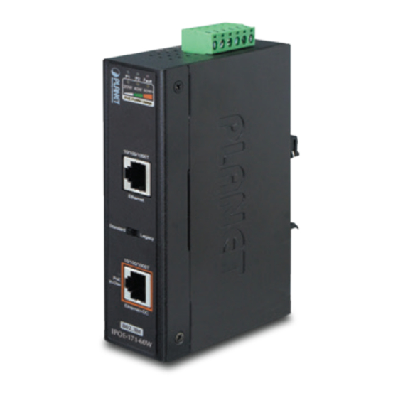
Page 7: Product Outlook
Ethernet+DC Ethernet+DC 802.3bt PoE ++ 802.3bt PoE ++ IPOE-171-60W IPOE-171-95W Figure 1: IPOE-171-60W outlook Figure 2: IPOE-171-95W outlook IPOE-171-60W LED Indicators: Color Function Green Lights to indicate power 1 has power. Green Lights to indicate power 2 has power. - Page 8 Amber Lights to indicate the device is providing PoE power. Monitor DC input voltage: When user powers on IPOE-171-60W, the injector will detect the DC input voltage and then PoE Usage LED will flash three times. 20W: Flashing three times means the DC input voltage is 48~50.9V.
- Page 9 30W: 1. Off to indicate the PoE usage is less than 14W. 2. Blinks to indicate that the PoE usage is around 15W to 29W. 3. Lights to indicate the PoE usage is more than 30W. 60W: 1. Blinks to indicate that the PoE usage is around Amber Usage 45W to 59W. 2.
-
Page 10: Industrial Poe++ Injector Upper Panel
1 2 3 4 5 6 DC Input: 48-54V , 2A max. PWR1 Alarm PWR2 Figure 3: IPOE-171-60W upper panel. Max. Fault Alarm Loading: 24V, 1A 1 2 3 4 5 6 DC Input: 12-54V , 6A max. PWR1 Alarm PWR2 Figure 4: IPOE-171-95W upper panel. - Page 11 Step 2: Tighten the wire-clamp screws for preventing the wires from loosening. Power 1 Alarm Power 2 Figure 6: PWR1 & PWR2 Pins of Terminal Block. 1. The wire gauge for the terminal block should be in the range between 12 ~ 24 AWG. 2.
-
Page 12: Wiring The Fault Alarm Contact
3.4 Wiring the Fault Alarm Contact The fault alarm contacts are in the middle of the terminal block connector as the picture shows below. After inserting the wires, the IPOE-171 series will detect the fault status of the power failure and then form an open circuit. -
Page 13: Mounting Installation
This section describes how to install the industrial device and make connections to it. Please read the following sections and perform the procedures in the order being presented. In the installation steps below, this manual uses PLANET Industrial Switch as an example. The steps for PLANET Industrial... -
Page 14: Side Wall-Mount Plate Mounting
4.3 Side Wall-mount Plate Mounting * The above pictures are for illustration only. 4.4 Grounding the Device Users MUST complete grounding wired with the device; otherwise, a sudden lightning could cause fatal damage to the device. Max. Fault Alarm Loading: 24V, 1A 1 2 3 4 5 6 DC Input: 12-54V... -
Page 15: Hardware Installation
1. In the installation steps below, this manual uses the IPOE-171-60W as an example. Except the input voltage, the steps for the IPOE-171-95W are similar. 2. Note that the input power range of the IPOE-171-60W Note is 48 ~ 54V DC and the input power range of IPOE- 171-95W is 12 ~ 54V DC. - Page 16 1000BASE-T UTP with PoE Power Line (DC) Figure 9: Architecture of connected IEEE 802.3at/bt device Once the IPOE-171-60W detects the existence of an IEEE 802.3at/bt device, the PoE-in-Use LED indicator will be steadily on to show it is providing power.
-
Page 17: Customer Support
6. Customer Support Thank you for purchasing PLANET products. You can browse our online FAQ resource at the PLANET Web site first to check if it could solve your issue. If you need more support information, please contact PLANET support team. - Page 18 FCC Statement NOTE: This equipment has been tested and found to comply with the limits for a Class A digital device, pursuant to part 15 of the FCC Rules. These limits are designed to provide reasonable protection against harmful interference when the equipment is operated in a commercial environment.
- Page 19 WEEE Warning To avoid the potential effects on the environment and human health as a result of the presence of hazardous substances in electrical and electronic equipment, end users of electrical and electronic equipment should understand the meaning of the crossed-out wheeled bin symbol. Do not dispose of WEEE as unsorted municipal waste and have to collect such WEEE separately.
Need help?
Do you have a question about the IPOE-171-60W and is the answer not in the manual?
Questions and answers