Table of Contents
Advertisement
Quick Links
WARNING: FIRE OR EXPLOSION HAZARD
Failure to follow safety warnings exactly could result in serious injury, death, or property damage.
- Do not store or use gasoline or other flammable vapors and liquids in the vicinity of this or any
other appliance.
- WHAT TO DO IF YOU SMELL GAS
• Do not try to light any appliance.
• Do not touch any electrical switch; do not use any phone in your building.
• Leave the building immediately
• Immediately call your gas supplier from a neighbor's phone. Follow the gas supplier's
instructions.
• If you cannot reach your gas supplier, call the fire department.
- Installation and service must be performed by a qualified installer, service agency or the gas supplier.
A barrier designed to reduce the risk of burns from
the hot viewing glass is provided with this appliance
and shall be installed for the protection of children
and other at-risk individuals.
This appliance may be installed in an aftermarket, permanently located, manufactured home
(USA only) or mobile home, where not prohibited by local codes.
This appliance is only for use with the type of gas indicated on the rating plate. A conversion
kit is supplied with the appliance.
INSTALLER: Leave this manual with the appliance.
CONSUMER: Retain this manual for future reference.
Travis Industries, Inc.
Copyright 2016, T.I.
Radiant Plus MV
Large Insert
Owner's Manual
HOT GLASS WILL CAUSE
BURNS
DO NOT TOUCH GLASS
UNTIL COOLED
NEVER ALLOW CHILDREN
TO TOUCH GLASS
12521 Harbour Reach Dr., Mukilteo, WA 98275
$10.00
Direct Vent Fireplace Insert
Masonry or Factory-Built
Residential or Mobile Home
French language manuals at travisindustries.com
Manuels de langue Française à travisindustries.com
4170202
Report # 0028GN101S
Omni-Test Laboratories, Inc.
Portland, Oregon
ANSI Z21.88-2014
CSA 2.33-2014
(Metal) Wood-Burning
Fireplace
www.travisproducts.com
100-01448
Advertisement
Table of Contents

Related Manuals for Lopi Radiant Plus MV


Summary of Contents for Lopi Radiant Plus MV
- Page 1 Radiant Plus MV Large Insert Owner’s Manual WARNING: FIRE OR EXPLOSION HAZARD Failure to follow safety warnings exactly could result in serious injury, death, or property damage. - Do not store or use gasoline or other flammable vapors and liquids in the vicinity of this or any other appliance.
-
Page 2: Introduction
Or, mail your warranty card to: service of any type. Travis Industries House of Fire 12521 Harbour Reach Dr. Model: Radiant Plus MV Large Mukilteo, WA 98275 Serial Number: Save Your Bill of Sale. To receive full warranty coverage, you will... -
Page 3: Table Of Contents
Table of Contents Introduction ............2 Glass Frame Removal and Installation ..21 Important Information ........2 Glass Frame Removal and Installation (continued) ............. 22 Listing Details ........... 2 Face Installation ..........23 Features ............ - Page 4 Safety Precautions Failure to follow all of the requirements may result in property damage, bodily injury, or even death. Young children should be carefully supervised when they are in the same room as the appliance. Toddlers, young children and others may be susceptible to accidental contact burns.
- Page 5 Safety Precautions Safety Warnings (continued) Because this heater can be controlled by a thermostat there is a possibility of the heater turning on and igniting any items placed on or near the appliance. Light the heater using the built-in igniter. Do not use matches or any other external device to light your heater.
-
Page 6: Features
Features and Specifications Features Installation Options Works During Power Outages Residential or Mobile Home Fireplace Insert Blower Optional Masonry or Factory Built (Metal) Wood- Standing Pilot Burning Fireplace Optional Remote Thermostat Natural Gas or Propane Variable-Rate Heat Output Heating Specifications Natural Gas Propane... -
Page 7: Installation Warnings
Installation (for qualified installers only) Installation Warnings Failure to follow all of the requirements may result in property damage, bodily injury, or even death. This heater must be installed by a qualified installer who has gone through a training program for the installation of direct vent gas appliances. ... -
Page 8: Fireplace Requirements
Installation (for qualified installers only) Fireplace Requirements Insert must be placed within a code-conforming masonry fireplace or tested and listed factory- built (metal) wood-burning fireplace. Repair any fireplace damage prior to installation. Because the insert may use an optional circulation blower, clean the fireplace, smoke shelf, and chimney prior to installation. -
Page 9: Factory-Built (Metal) Wood-Burning Fireplace Requirements
Installation (for qualified installers only) Factory-Built (Metal) Wood-Burning Fireplace Requirements The damper ("A") and grate (with log set) ("B") must be removed (see the illustration below). The smoke shelf ("C"), internal baffles ("D"), screen ("E"), masonry lining or refractory ("G" & "I"), and metal or glass doors ("F") may be removed (if applicable). -
Page 10: Leveling Legs
Installation (for qualified installers only) Leveling Legs This heater includes front and rear leveling legs to accommodate fireplaces with a step-down firebox. Loosen these bolts, slide the legs to the correct position, then re-tighten the bolts. 3/8" Wrench Electrical Requirements for Optional Blower ... -
Page 11: Clearances
Installation (for qualified installers only) Clearances Due to the high temperature of the heater, it should be located out of traffic and away from furniture and draperies. Side Wall Minimum Clearances k Sidewall to Insert 5” (127mm) l Side Facing (non-combustible) 5”... -
Page 12: Gas Line Requirements
Installation (for qualified installers only) Gas Line Requirements MASSACHUSETTS INSTALLATIONS - WARNING: THIS PRODUCT MUST BE INSTALLED BY A LICENSED PLUMBER OR GAS FITTER WHEN INSTALLED WITHIN THE COMMONWEALTH OF MASSACHUSETTS. OTHER MASSACHUSETTS CODE REQUIREMENTS: Flexible connector must not be longer than 36 inches. ... -
Page 13: Vent Requirements
Installation (for qualified installers only) Vent Requirements Travis Industries manufactures a vent kit specifically for this insert (sku 96200330). It includes 30’ (10M) of vent, hose clamps, and a prairie cap. The flashing on the cap is 18” (458mm) by 18” (458mm). ... -
Page 14: Vent Restrictor
Installation (for qualified installers only) Vent Restrictor WARNING: Restrictor adjustment should only be done by a qualified installer. Most installations do not require vent restrictor adjustment. Only those installations determined to be over-drafting require adjustment. The best indication of over-drafting is a hyper-active flame pattern (flames move too quickly). -
Page 15: Vent Installation
Installation (for qualified installers only) Vent Installation Secure the vent to the fireplace insert and termination kit using screws. Intake "I" Exhaust "E" 3" (76mm) dia. Gas Liner (3" 76mm) (3" 76mm) Approved Additional Coaxial Sections May Be Added (support as needed) Inlet Exhaust Inlet... -
Page 16: Vent Configurations
Installation (for qualified installers only) Vent Configurations Inlet & Exhaust Re-Line Exhaust Only Re-Line Direct Vent Cap (either high wind or Prairie) 6-5/8" to 3" & 3" Colinear Adapter & Flashing Exhaust Exhaust Any cracks or damage inside the chimney must be Inlet repaired. -
Page 17: Vent Connector Removal And Installation
Installation (for qualified installers only) Vent Connector Removal and Installation The vent connector is shipped attached to the insert, but may be removed to facilitate tight installations. See the directions below for installation. 1. Route the flex vent through the chimney from above (leave an extra 3' at the top). Make sure the flex is thoroughly stretched. -
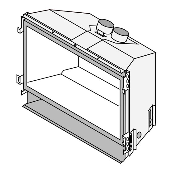
Page 18: Vent Connector Removal And Installation (Continued)
Installation (for qualified installers only) Vent Connector Removal and Installation (continued) The vent connector may be removed. This screw holds the connector in place. 1/4" Nutdriver When replacing, make sure the gasket under the connector remains in place. The vent connector slides back and disengages from the three tabs on top of the insert. Connect the flex vent (exhaust and intake) to the vent connector (use self-drilling screws or hose clamps). - Page 19 Installation (for qualified installers only) The vent connector, when hanging from the chimney, may be grasped by reaching above the insert. Carefully move the connector forward, making sure all 3 tabs insert through the connector. Secure the vent connector to the insert using the screw removed earlier. ©...
-
Page 20: Surround Panel Installation
Installation (for qualified installers only) Surround Panel Installation NOTE: The insert may be installed without surround panels. PANEL SIZE HEIGHT WIDTH PART # Small 30-1/2” 42” 96100562 Large 34” 44” 96100563 1. The insert should be in position with gas line and flue and intake connections attached, but pulled out slightly to allow panel installation. -
Page 21: Glass Frame Removal And Installation
Finalizing the Installation Glass Frame Removal and Installation The appliance must be completely cool before removing the glass. Do not strike or slam the glass. Open the four latches holding the glass Latch frame in place (start with the two below Push in on Top of the glass) - follow the directions shown... -
Page 22: Glass Frame Removal And Installation (Continued)
Finalizing the Installation Glass Frame Removal and Installation (continued) The glass latch can come loose from the glass frame. This occurs when the latch is turned 1/8 turn when disengaged from the unit. Follow the directions below to re-install the latch if it comes loose. Hold the latch at an angle and insert it into the slot on the glass frame. -
Page 23: Face Installation
Finalizing the Installation Face Installation A barrier designed to reduce the risk of burns from the hot viewing glass is provided with this appliance and shall be installed for the protection of children and other at-risk individuals. If the barrier becomes damaged, the barrier shall be replaced with the manufacturer’s barrier for this appliance. -
Page 24: Log Installation
Finalizing the Installation Log Installation The logs are fragile, especially after being exposed to heat. Make sure the gas control valve is “OFF” and the heater is cool prior to conducting service. Failure to position the parts in accordance with diagrams or failure to use only parts specifically approved with this appliance may result in property damage or personal injury. - Page 25 Finalizing the Installation The left log has two holes on the bottom. Place the log so the holes fit over the two mounting studs on the left log stand. The right log has two holes on the bottom. Place the log so the holes fit over the two mounting studs on the right log stand.
- Page 26 Finalizing the Installation The left cross log has one hole on the bottom. Place the log so the hole fits over the left pin on the rear log. The front of the log rests on the left log (see picture for orientation). The right cross log has one hole on the bottom.
-
Page 27: Rock Wool Placement
Finalizing the Installation Two twigs are included for the front of the firebox. Place them at the front of the firebox as shown below (do not place them over any burner holes). Rock Wool Placement The included rock wool is placed on top of the burner to enhance the glow from the burner. The rock wool works best when it is applied in a very thin, porous layer. -
Page 28: Steps For Finalizing The Installation
Finalizing the Installation Steps for Finalizing the Installation 1. Remove the glass (see page 21). NOTE: If using propane (LP) convert the appliance prior to installing the media. 2. We recommend you purge the gas line at this time (with the glass removed). This allows gas to be detected once it enters the firebox, ensuring gas does not build up. -
Page 29: Air Shutter Adjustment
Finalizing the Installation 9. Check the air shutter following the directions below. Air Shutter Adjustment Let the heater burn for fifteen minutes (make sure the media and glass are in place). The flames should be yellow with no sooting. Adjust the air shutter, if necessary, to achieve the correct looking flame. Correct Not Enough Air Too Much Air... -
Page 30: Before You Begin
Operation Before You Begin Read this entire manual before you use your new heater (especially the section "Safety Precautions" on pages 4 & 5). Failure to follow the instructions may result in property damage, bodily injury, or even death. Turn off the main gas supply to the appliance during appliance installation or maintenance. -
Page 31: Starting The Pilot
Operation Starting the Pilot Remove the glass frame before starting the pilot. The pilot flame is required to ignite the main burners (it also plays a safety role). It should be left on once lit. It will stay lit unless the gas control valve is turned to "OFF". -
Page 32: Starting The Heater For The First Time
Operation Starting the Heater for the First Time Burn the heater at a high setting with the blower off for an extended period (up to 48 hours). This will cure the painted surfaces. Fumes from the paint curing and oil burning off the steel will occur. This is normal. -
Page 33: Adjusting The Blower Speed (Optional)
Operation Adjusting the Blower Speed (Optional) The optional blower helps transfer heat from the heater into the room. It will not turn on until the heater is up to temperature (approximately 10 minutes after starting). See the illustration below for instructions on adjusting the blower speed. -
Page 34: Maintaining Your Heater's Appearance
Maintenance DANGER HIGH VOLTAGE: Disconnect power before attempting maintenance or repair. Maintaining Your Heater's Appearance The appliance must be completely cool prior to conducting service. Cleaning The Glass The glass may be cleaned with a non- abrasive cleaner. To clean the inside of the glass, simply remove the glass frame, place it on a non-scratching surface, and clean the surface. -
Page 35: Troubleshooting Table
Maintenance Troubleshooting Table Problem: Possible Cause: Don't Call for Service Until You: A gas shut off valve is turned off Check all gas shut off valves Pilot Will Not Light The gas control knob isn't turned to "PILOT" See "Starting the Pilot Light" Step C The valve control knob isn't pushed in See "Starting the Pilot Light"... -
Page 36: Replacement Parts List
Maintenance Replacement Parts List Caution: Use only Travis Industries replacement parts. Do not use substitute materials. Warning: Do not operate appliance with the glass front removed, cracked, or broken. Replacement of the glass should be done by a licensed or qualified service person. Replacement Glass Part # 250-01169 Contact your local Travis Industries Dealer for a Replacement Parts List Wiring Diagram... -
Page 37: Safety Label
Safety Label Safety Label The safety (listing) label is attached to the operating tag (chained to the heater near the gas control valve). A copy is shown below © Travis Industries 4170202 100-01448... -
Page 38: Conditions & Exclusions
Limted 7 Year Warranty Register your TRAVIS INDUSTRIES, INC. Limited 7 Year Warranty online at traviswarranty.com, or complete the enclosed Warranty card and mail it within ten (10) days of the appliance purchase date to: TRAVIS INDUSTRIES, INC., 12521 Harbour Reach Drive, Mukilteo, WA 98275. TRAVIS INDUSTRIES, INC. warrants this gas appliance (appliance is defined as the equipment manufactured by Travis Industries, Inc.) to be defect-free in material and workmanship to the original purchaser from the date of purchase as follows: Check with your dealer in advance for any costs to you when arranging a warranty call. -
Page 39: Lp (Propane) Conversion Instructions
Optional Equipment for qualified installers only) LP (Propane) Conversion Instructions WARNING This conversion kit shall be installed by a qualified service agency in accordance with the manufacturer’s instructions and all applicable codes and requirements of the authority having jurisdiction. If the information in these instructions is not followed exactly, a fire, explosion or production of carbon monoxide may result causing property damage, personal injury or loss of life. - Page 40 Optional Equipment for qualified installers only) 4. Remove the burner and place it aside. 5. Install the LP (propane) pilot orifice following the instructions below. (a) Use a 7/16” open-end wrench to remove the pilot hood. (b) Remove and discard the Natural Gas (NG) orifice. Place the LP orifice in the pilot assembly then replace the pilot hood, tightening the pilot hood until it is snug (do not over-tighten).
- Page 41 Optional Equipment for qualified installers only) 7. Remove the regulator from the front of the gas control valve. Replace with the propane regulator, using the new gasket and screws included with the regulator. NOTE: Leak test this area after the heater is installed, gas is connected, and the main burner is lit.
-
Page 42: Optional Firebacks
Optional Equipment for qualified installers only) Optional Firebacks WARNING Turn off gas to the appliance and make sure it has fully cooled prior to conducting service. Slide the rear fireback behind the baffle on top of the firebox then pivot it into place. It rests on the shelf at the back of the firebox. Remove the glass frame MAKE SURE THE FULL BRICK IS AT THE TOP and logs (see the manual... -
Page 43: Optional Blower
Optional Equipment for qualified installers only) Optional Blower Installation WARNING: Do not plug the blower in until it is fully installed and grounded. Do not connect 110-120 VAC to the gas control valve or wiring system of this appliance. NOTE: Install the blower after the insert is in place. - Page 44 Index Additional Items Required ........7 LP Conversion Instructions ......39 Before You Begin ..........30 Maintaining Your Heater's Appearance ... 34 Clearances ............11 Normal Operating Odors ........33 Dimensions ............6 Normal Operating Sounds ....... 33 Electrical Requirements for Optional Blower ... 10 Order of Installation..........
Need help?
Do you have a question about the Radiant Plus MV and is the answer not in the manual?
Questions and answers