
Related Manuals for Brother MD-602


Summary of Contents for Brother MD-602
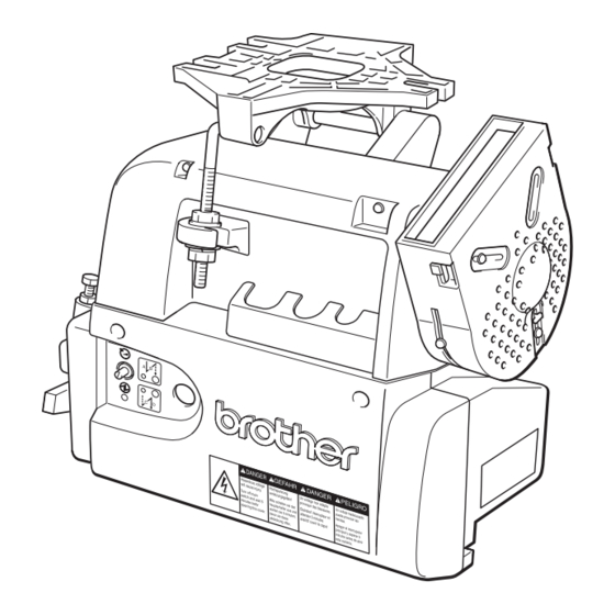
- Page 1 MD-600 Series AC Servomotor for Industrial Sewing Machines SERVICE MANUAL MD-602 (Single-Phase Power Specifications) MD-612 (Three-Phase Power Specifications)
-
Page 2: Table Of Contents
Contents SAFETY INSTRUCTIONS SAFETY INDICATIONS AND THEIR MEANINGS ..............CAUTIONS WITH REGARD TO SAFETY ................WARNING LABEL ........................iii Outline Outline ..........................Operation panel and options ..................Model configuration ......................Explanation of the name plate ..................Instruction Installation ........................Installing the motor to the work table ..............Attatching the belt .................... - Page 3 10.4 Setting the control box speed setting for the head ..........25 11. Changing the function settings ..................26 11.1 Example for changing the memory switch setting ..........26 11.2 Example for changing the parameter setting ............26 12. Adjustments ........................27 12.1 Synchronizer Model DB2-B737, B748, B774, B791 ..........
-
Page 4: Safety Instructions
Thank you for purchasing this Brother general-purpose sewing machine motor. Before using the motor, please be sure to read the Safety Instructions and the explanations of how to use the motor which are contained in this manual. Furthermore, because we are continually improving our products as a result of continuing research, the specifications for the product which you have purchased may differ slightly from those listed in this manual. -
Page 5: Cautions With Regard To Safety
Exposure to direct sunlight may cause problems with correct operation of the sewing machine. In the event of an electrical storm, turn off the power and disconnect the power cord from the wall outlet. Lightning may cause problems with correct operation of the sewing machine. MD-602, 612... -
Page 6: Warning Label
The warning label shown below is affixed to the cover of the control box. Please follow the instructions on the label at all times when using the motor. If the label has been removed or is difficult to read, please contact your nearest Brother dealer. -
Page 7: Outline
• The rated output is 400W. • The motor torque has been greatly increased compared to the MD601/611. 1.2 Combination with Brother sewing machines 1. Single needle lockstitch machines (forward rotation) B737, (B201) B791, B774, B722, B724, B748A, B798, B728, B772A, B778A, B781, B852, B853, B854, B883 2. -
Page 8: Operation Panel And Options
Code no. of model type operation panel Foot plug J02824-001 F-20 137-207-711-11 B737MK II built-in F-40 137-207-712-11 F-100 137-207-713-11 BF-20 137-207-811-11 B201 built-in BF-40 137-207-812-11 BF-100 137-207-813-11 Operation panel F-20 137-207-711-10 (without install attached F-40 137-207-712-10 plate) F-100 137-207-713-10 MD-602, 612... -
Page 9: Model Configuration
SJT + OCR Canada B883 B848 220V FOR B883 General Overlock B772A For 3-phase B778A Voltage Switch Destination B781 200V Domestic specifications Japan 220V Standard part 220V With OCR 220V With SJT Canada 220V With SJT & OCR Canada MD-602, 612... -
Page 10: Explanation Of The Name Plate
MD-6 * 2 * - * VOLTS ********* HERTZ 50/60 CONTROL BOX FOR MD-60A qwert TYPE B MADE IN JAPAN yuio!0 ! 1 ! 2 ! 3 ! 4 display BROTHER INDUSTRIES, LTD. phase voltage phase voltage Motor name plate single 110V SINGLE single 220V... -
Page 11: Installation
2. An abnormal noise may be heard due to belt slip- page. 3. The belt may become too loose and contact the cover. 4. When sewing heavy materials, the belt may slip on the pulley and the sewing machine may stop. MD-602, 612... -
Page 12: Installing The Belt Cover
4. After adjusting, tighten the screw e. Note: The finger guard is a safety mechanism that prevents fingers from being caught in the belt. Change the position of the finger guard r to match the direction of rotation of the motor pulley. MD-602, 612... -
Page 13: Connecting The Cords
• Connect the 12-pin plug and the 6-pin plug. • Close the cover w (be careful not to clamp the cord) and tighten the two screws q. • Connect the synchronizer cord e. MD-602, 612... - Page 14 Never short circuit the output terminals. Note: If using an automatic presser foot lifter, set the DIP switch SW1-3 on the circuit board to ON. (Refer to “7.5.2 Other DIP switch functions”.) MD-602, 612...
-
Page 15: Installing The Head Lamp
7. Connect the synchronizer cord q. Note: When an external operation panel is installed, the backtacking function of the control circuit board will be disabled, so use the external operation panel to carry out backtacking. MD-602, 612... -
Page 16: Adjusting The Treadle Unit
If the treadle is pressed forward, the sewing machine will operate after the presser foot lowers. Note: The presser foot can be raised and lowered by returning the treadle only from when the power switch is turned on to when the knee switch is operated. MD-602, 612... - Page 17 • The presser foot will lower when the treadle is returned to the neutral position q. • The presser foot will lower if the treadle is gently pressed to the position y while the presser foot is raised. MD-602, 612...
-
Page 18: Adjusting The Treadle
• When changing the spring positions from F to E and from C to D, you must remove the three screws q of the treadle unit and disconnect the treadle unit from the control box before changing the spring positions. MD-602, 612... -
Page 19: Using The Control Box
Control box rating plate (Example: Single-phase 220 V tions. specifications) 1. Model q MD-602 (for single-phase power supply) MD-612 (for three-phase power supply) S I N G L E P H A S E Power The model should match the power supply phase w. -
Page 20: Control Box Dip Switch Setting Procedure
5 hauptschalter aus und attendre 5 minutes Apagar el interruptor minutes before warten sie 5 minuten, avantd' ouvrir le capot principal y esperar 5 opening this cover. bevor sie diese minutos antes de abrir abdeckung öffnen. esta cubierta. MD-602, 612... -
Page 21: Description Of Functions
LED r switches off and end backtacking can no longer be carried out. The end backtack key w can be used to turn end backtacking on and off at any time. End backtack key End backtack LED MD-602, 612... - Page 22 At the time of shipment from the factory, DIP switches A, B, C and D are all set to OFF. As a result, the number of stitches is set to 2 for each of A, B, C and D. When using an operation panel, backtacking functions using the control box are all disabled. MD-602, 612...
-
Page 23: Periodic Checks
• Clean the dust out of the dust cover at periodic intervals. If the dust cover becomes blocked, there is the danger that the motor may overheat. • If not using the motor for long periods, turn off the power and disconnect the motor from the power supply. MD-602, 612... -
Page 24: Connecting Options
9. Securely insert the 9-pin connector !5 for the standing pedal into the 9-pin connector o. 10. Close the cover w (be careful not to clamp the cord) and tighten the two screws q. 11. Connect the synchronizer cord e. MD-602, 612... - Page 25 • Connector wiring diagram VARIABLE-SPEED PEDAL TWO SPEED PEDAL HIGH. S HIGH. S TRIMMER TRIMMER INPUT LOW. S LIFT LIFT When the switch for the target function has been turned ON, turn the other OFF. MD-602, 612...
-
Page 26: Connecting The Material Edge Sensor
3. Insert the sensor II connector t into connector r in the the machine. 4. Install the operation panel q onto the machine. operation panel. 4. Install the sensor II y and operation panel q onto the mounting bracket w as shown in the illustration. MD-602, 612... -
Page 27: Using The Operation Panel F-40
When this key is pressed, the number of stitches set for A, B, C and D (0 – 9) will be sewn as Continuous continuous backtack stitches. After the machine finishes sewing one A-B-C-D cycle, the backtack key thread is automatically trimmed. The number of start and end backtack stitches can be set independently of each other. MD-602, 612... - Page 28 If the treadle is pressed to the neutral position while the “ ” indicator is illuminated, the needle will drop below the needle plate and stop (needle down stop). Half stitch key This key is used to raise or lower the needle when machine operation is interrupted. MD-602, 612...
-
Page 29: Changing The Head Settings
3000 (6500) rpm B722-3 4700 B722-5 4000 B724-5 4000 B748-5 4000 B748-7 3000 3500 (7000) rpm 4000 (7500) rpm B798 2000 B772 4700 B778 4700 B781 4000 4500 (8000) rpm 4700 (8500) rpm B852 4500 B883 6000 8000 MD-602, 612... -
Page 30: Setting The Control Box Head Setting For The Head
1) When chaning the setting for DIP switches 1-2, 1-5 or 6 Initial value: [ 7 3 7 3 ] when switch 1-5 is OFF (single needle) [ 8 4 2 3 ] when switch 1-5 is ON (twin needle) MD-602, 612... -
Page 31: Setting The Control Box Speed Setting For The Head
DIP switch 1 or the speed set in speed setting mode [ S P ] The speed can be changed easily using the sewing speed key on the operation panel. • The automatic sewing speed can only be set to be lower than the maximum sewing speed. MD-602, 612... -
Page 32: Changing The Function Settings
[ P A ]. ([ P A 8) Using the [B+] key, set the [AB] display to [ E n ], and then press the [ ] key. The [ABCD] display will disappear, and the setting will be completed. MD-602, 612... -
Page 33: Adjustments
(Improper clearance causes improper machine operation.) When the synchronizer is out of order... Turn off the power switch and disconnect the synchronizer cord. Use the machine with standard function (without thread trimming) until the synchronizer is replaced. MD-602, 612... -
Page 34: Troubleshooting Guide
• If there seems to be a malfunction, first check the machine as described below. If the problem remains unresolved, turn off the power and contact your nearest Brother dealer. When using a model with the operation panel if an error displays on the operation panel refer to “13.1 Error display and details”. - Page 35 If the sewing machine does not stop, Replace the control box. there is a problem with the control box. Needle up position Needle down position MD-602, 612...
-
Page 36: Error Display And Details
If the sewing machine has been running continuously Time overrun for 3 minutes, it is stopped as a safety measure. Control circuit board memory All displays flash. Replace the control box or control circuit board. element is faulty. MD-602, 612... -
Page 37: Control Box Troubleshooting Guide
Something is wrong with the Replace synchronizer smoothly. Motor rotate by cord and check encoder signals. doing inching. It rotate smoothly It does not rotate Motor is broken down or resis- Motor smoothly. tance value abnormal Others Control PCB MD-602, 612... - Page 38 Power transformer When power SW is ON, LED Fuse F101, F102 blown? Check resistance value at the Replace transformer (Red) does not illuminate. primary side of transformer. Is there about 15ohm? Check BD101. Replace BD101 MD-602, 612...
-
Page 39: Checking The Machine Solenoids
1. Remove the motor cord (4P connector) from the connector part of the power board. 2. Measure with the tester set in the resistance range × 1 as follows. GREEN/YELLOW 2.6 Ω 2.6 Ω 2.6 Ω BLACK WHITE MOTOR MD-602, 612... -
Page 40: Vr1 & Vr2 Setting Of Treadle Unit
14. VR1 & VR2 setting of treadle unit PS-INV Assy (MD-602, 612) After changing this circuit board. Please adjust the volume (VR1, VR2) since we suppose that the voltage of each position may change due to the aberration of position of magnet and hole element when you set this circuit board onto the treadle base. - Page 41 Stroke – VC (analog voltage) Chart Stroke – rpm chart MD-602, 612...
-
Page 42: Explanation Of Each Mode
Initialize to speed of head data set in head setting mode. Initialization of speed data [ S P ] ] of B Not initialize by pressing [ ], and instead move to stitching mode. [ E n ] End code Stitching mode ] of B MD-602, 612... -
Page 43: Head Setting Mode
SW1-6, 7, 8 setting. (Note 2) The settings will be registered when the [ ] key is pressed. If the settings are not to be changed, turn the power switch ON again without pressing the [ ] key. MD-602, 612... -
Page 44: Memory Switch Setting Mode And Parameter Setting Mode, Etc
] of B sing the [ [ C P ] Input/output check mode key, the stitching mode is returned ] of B [ r o ] ROM version mode ] of B End code [ E n ] MD-602, 612... - Page 45 ROM version display [ r o ] ] of B End the setting mode menu 2 when the [ ] key is pressed, and return to the setting mode menu 1. END code [ E n ] ] of B MD-602, 612...
-
Page 46: Stitching Speed Setting Mode
The head settings will also be initialized. a) When SW1-5 is set to OFF (Initialized to head setting [ 7 3 7 3 ] ) b) When SW1-5 is set to ON (Initialized to head setting [ 8 4 2 3 ] ) MD-602, 612... -
Page 47: Operational Instructions
• The motor drive power voltage is constantly checked, and the required control is executed. The following voltages are detected. [ O u ] (overvoltage): Error that occurs when 304VAC is exceeded. [ O L ] (overload): Error that occurs when a level 290VAC or more continues for 160ms. MD-602, 612... -
Page 48: Memory Switch List
[ ] OFF, Actuator switch = Reverse stitch correction switch [ ] ON, Actuator switch = 1 stitch correction switch [ ] OFF, Actuator switch = Normally switch [ ] ON, Actuator switch = 1 stitch correction switch MD-602, 612... - Page 49 Holding time control of presser lifter is not ON by timer (ON time is [ F1 ] of setting timer) Chopping duty of presser lifter setting Transistor controlling 2.5ms 2.5ms Upper and lower transistor ON/OFF at a same time Upper transistor keep ON, lower transistor ON/OFF. MD-602, 612...
- Page 50 * Reduction of incorrect forward treadle repressing operation caused by rebound of treadle from backward repressing Presser foot does not lower when treadle is pressed forward 1st step. Presser foot lowers when treadle is pressed forward 1st step. (Not used) * Normally OFF MD-602, 612...
- Page 51 When one is turned to ON, the other will be set to OFF. IF all are set to OFF, the puller output will be applied. ON when presser or reverse solenoid is ON. OFF after the No. of stitches (parameter [C0]) or after 10 seconds have passed. MD-602, 612...
- Page 52 Treadle operation valid after standing work (during simultaneous operation, standing work has priority) Treadle operation invalid after standing work (Not used) Normally OFF (Not used) Normally OFF (Not used) Normally OFF (Not used) Normally OFF (Not used) Normally OFF MD-602, 612...
-
Page 53: Parameter List
(50 to 500ms) * When memory switch [68] is set to ON Temporary stop position during reverse change timing 00 to 23 (Number of pulses from needle UP signal) (pulse) (pulse) * When memory switch [68] is set to ON MD-602, 612... - Page 54 (not used) Overtime detection time 00 to 30 (×1) * When memory switch [16] is set to OFF (function valid) (3 min) (0 to 30 min) * Overtime not detected when 00 is set 00 to 99 (not used) MD-602, 612...
- Page 55 (When the numerical value is large, the variable speed area will increase) 04 to 50 (don’t change) 05 to 30 (don’t change) 05 to 30 (don’t change) 00 to 70 (don’t change) 01 to 23 (don’t change) 00 to 70 (don’t change) MD-602, 612...
- Page 56 01 to 99 (don’t change) Parameters [ M0 ] ∼ [ M5 ], [ M8 ] ∼ [ MQ ] must not be changed. If they are changed by mistake, initialize the (Note) parameters with the initialization mode. MD-602, 612...
-
Page 57: Panel Display Table
19. Panel display table The following alphabetic characters and symbols are displayed on the operation panel. 7-segment display 7-segment display 7-segment display 7-segment display MD-602, 612... -
Page 58: How To Remove The Control Box
In the same manner, loosen the screws on the opposite i. Slide the control box to the right. side by about half. (Two places) o. Lower the control box. !0 . Install the control box, following the above instructions in reverse. MD-602, 612... -
Page 59: Control Box Block Diagram
MD-602, 612... -
Page 60: Control Pcb Assembly Diagram
MD-602, 612... -
Page 61: Control Pcb Circuit Diagram (1/3) (2/3) (3/3)
MD-602, 612... - Page 62 MD-602, 612...
- Page 63 MD-602, 612...
-
Page 64: Power Pcb Assembly Diagram (1-110/120)
MD-602, 612... -
Page 65: Power Pcb Circuit Diagram (1-110/120) (1/2)
MD-602, 612... -
Page 66: Power Pcb Assembly Diagram (1-220/230-240)
MD-602, 612... -
Page 67: Power Pcb Circuit Diagram (1-220/230-240) (1/2)
MD-602, 612... -
Page 68: Power Pcb Assembly Diagram (3-220)
MD-602, 612... -
Page 69: Power Pcb Circuit Diagram (3-220) (1/2)
MD-602, 612... -
Page 70: Power Pcb Assembly Diagram (1-230(Ce))
MD-602, 612... -
Page 71: Power Pcb Circuit Diagram (1-230(Ce)) (1/2)
MD-602, 612... -
Page 72: Power Pcb Circuit Diagram (2/2)
MD-602, 612... -
Page 73: Panel Pcb Assembly Diagram
MD-602, 612... -
Page 74: Panel Pcb Circuit Diagram
MD-602, 612... -
Page 75: Treadle Pcb Assembly Diagram, Circuit Diagram
MD-602, 612... - Page 76 BROTHER INDUSTRIES, LTD. NAGOYA, JAPAN Printed in Japan J90113-001 2001. 06.
Need help?
Do you have a question about the MD-602 and is the answer not in the manual?
Questions and answers