
Related Manuals for Sega Harley Davidson & L.A Riders


Summary of Contents for Sega Harley Davidson & L.A Riders
- Page 1 1ST PRINTING JAN.- 1998 OWNER’S MANUAL STD TYPE SEGA ENTERPRISES, USA MANUAL NO. 4200-6367...
- Page 2 Warranty Your new Sega Product is covered for a period of 90 days from the date of shipment. This certifies that the Printed Circuit Boards, Power Supplies and Monitor are to be free of defects in workman- ship or materials under normal operating conditions. This also certifies that all Interactive Control Assemblies are to be free from defects in workmanship and materials under normal operating condi- tions.
-
Page 3: Table Of Contents
TABLE OF CONTENTS INTRODUCTION OF THE OWNERS MANUAL GENERAL PRECAUTIONS 1. PRECAUTIONS TO BE HEEDED FOR OPERATION 2. NAME OF PARTS 3. ACCESSORIES 4. ASSEMBLY AND INSTALLATION 9~14 5. PRECAUTIONS TO BE HEEDED WHEN MOVING MACHINE 6. CONTENTS OF GAME 16~18 19~30 7. -
Page 4: Introduction Of The Owners Manual
29” INCH COLR MONITOR INTRODUCTION OF THE OWNERS MANUAL SEGA ENTERPRISES, LTD., has for more than 30 years been supplying various innovative and popular amusement products to the world market. This Owners Manual is intended to provide detailed descriptions together with all the necessary installation, game settings and parts ordering information related to the HARLEY DAVIDSON U/R, a new SEGA product. -
Page 5: General Precautions 2~3
General Precautions Follow Instructions: All operating and use instructions should be followed. Attachments: Do not use attachments not recommended by the product manufacturer as they may cause hazards. Accessories: Do not place this product on an unstable cart, stand, tripod, bracket, or table. The product may fall, causing serious injury to a child or adult, and serious damage to the product. - Page 6 Safety Check: Upon completion of any service or repairs to this product, ask the service technician to perform safety checks to determine that the product is in proper operating condition. Heat: The product should be situated away from heat sources such as radiators, heat registers, stoves, or other prod- ucts (including amplifiers) that produce heat.
-
Page 7: Precautions To Be Heeded For Operation
1 . PRECAUTIONS TO BE HEEDED FOR OPERATION In order to prevent accidents, be sure to comply with the following points before and during operation. PRECAUTIONS TO BE HEEDED FOR OPERATION BEFORE STARTING THE OPERATION In order to avoid accidents, check the following before starting the operation: Check if all of the adjusters are in contact with the surface. - Page 8 PRECAUTIONS TO BE HEEDED DURING OPERATION To avoid injury and accidents, those who fall under the following catagories are not allowed to play the game: * Intoxidated persons * Pregnant women or those in the likelyhood od pregnancy. * Those who need assistasnce such as the use of an apparatus when walking. * Those who have high blood pressure or heart problems.
-
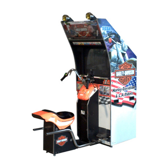
Page 9: Name Of Parts
2 . NAME OF PARTS BILLBOARD 29 INCH MONITOR CABINET COIN CHUTE DOOR CASHBOX DOOR SEAT CABI AC UNIT WEIGHT GAME SPECIFICATIONS WIDTH LENGTH HEIGHT 475 LBS. All measurements are in inches DURING SHIPPING 350 LBS. CABINET 31” 38” 78” 49 LBS. -
Page 10: Accessories
3 . ACCESSORIES... - Page 11 THE SHIPMENT METHOD DESCRIBED BELOW ONLY APPLIES TO ‘MODEL 3’ BOARDS CONTAINED IN THE FOLLOWING GAMES: LOST WORLD, VIRTUA FIGHTER 3, SUPER GT, SEGA BASS FISHING, STRIKER 2 HARLEY DAVIDSON !!NEVER SHIP MODEL 3 GAME BOARDS !!NEVER SHIP MODEL 3 GAME BOARDS...
-
Page 12: Assembly And Installation
4 . ASSEMBLING AND INSTALLATION Assembling should be performed as per this manual. Since this is a complex machine, erroneous assembling may cause damage to the machine, or malfunctioning to occur. When assembling, be sure to perform work by plural persons. Depending on the assembly work, there are some cases in which performing the work by a single person can cause personal injury or parts damage. - Page 13 Tightly fit the seat cabi to the cabinet in a manner to insert it in. Secure to the cabinet with 2 hexagon bolts and 2 truss screws. Connect the connector. (2P white) Install the joint lid. Secure the Joint lid with 4 screws.
- Page 14 SECURING IN PLACE (ADJUSTER ADJUSTMENT) Be sure to have all the Adjusters make contact with the surface. Un- less the Adjusters come into contact with the surface, the Cabinet can move of itself, causing an accident. This machine has 8 each of casters and adjusters (shown below). When the installation position is determined, cause the adjusters to come into contact with the floor directly, make adjustments in a manner so that the casters will be raised approximately 5mm.
- Page 15 POWER SUPPLY Ensure that the power cord is not exposed on the surface (passage, etc.). If exposed, they can be caught and are susceptible to damage. If damaged, the cord can cause an electric shock or short circuit. Ensure that the wiring position is not in the customer's passage way or the wiring has protective covering.
- Page 16 ASSEMBLING CHECK The TEST MENU allows for each part of the cabinet to be checked, the Monitor to be adjusted, and the coin and game related various functions to be performed. CPU ROM TEST Selecting the MEMORY TEST on the test mode menu screen causes the on-board memory to be tested automatically.
- Page 17 SOUND TEST In the TEST mode, selecting SOUND TEST causes the screen, on which sound related BD and wiring connec- tions are tested, to be displayed. be sure to check if the sound is satisfactorily emitted from each of speaker and ( 0 ) the sound volume is appropriate.
-
Page 18: Precautions To Be Heeded When Moving Machine
5 . PRECATIONS TO BE HEEDED WHEN MOVING THE MACHINE When moving the machine, be sure to pull out the plug from the power supply. Moving the machine with the plug as is inserted can damage the power cord and cause a fire or elec- tric shock. -
Page 19: Contents Of Game
6 . CONTENTS OF GAME The following are operations and responses obtained when the machine functions satisfactorily. Any functioning different fromt he following may have been caused by a certain fault. Immediately investigate and eliminate the cause of the malfunctioning to ensure satisfacory operation. The explanation herein mainly refer to the case where the game machine is used independently. - Page 20 Be seated. Insert coin(s). When one play worth of coin(s) is inserted, the Select mode appears. Select in order of BIKE and TRANSMISSION. Turn the handlebar to select and turn the ACCELORATOR GRIP to decide. When the Select Mode is displayed, countdown starts. At count 0, BIKE TRANSMISSION being selected are automatically decided.
- Page 21 Run towards the checkpoint by judging the route from the arrow and the NAVIGATION WINDOW. Passing the checkpoint within the time limit results in a Stage Clear. The time limit is extended and the next checkpoint is displayed. If the player fails to pass the checkpoint within the time limit, the game is over. Passing all of the checkpoints results in a Game Clear.
-
Page 22: Explanation Of Test And Data Display
7 . EXPLANATION OF TEST AND DATA DISPLAY By operating the switch unit, periodically perform the tests and data check. When installing the machine initially or collecting cash, or when the machine does not function correctly, perform checking in accordance with the explanations given in this section. The following shows tests and modes that should be utilized as applicable. -
Page 23: Power Supply Unit And Coin Meter
7 - 1 SWITCH UNIT AND COIN METER Never touch places other than those specified. Touching places not specified can cause electric shock and short circuit. Adjust to the optimum sound volume by considering the environmental requirements of the installation location. If the COIN METER and the game board are electrically disconnected, game play is not possible. -
Page 24: Test Mode
7 - 2 TEST MODE This mainly checks if the operation of the game BD is accurate, and allows for COIN ASSIGNMENTS/GAME ASSIGNMENTS setting and Projector adjustments. TEST MENU Push the TEST BUTTON to cause the follow- CPU MEMORY TEST ing TEST MENU to appear: VIDEO MEMORYTEST BOUNDRY SCAN TEST... -
Page 25: Video Memory Test
7 - 4 VIDEO MEMORY TEST VIDEO BOARD ROM TEST This allows the functioning of the VIDEO GOOD (VROM01) IC.26 ***** MEMORY IC’s on the IC board to be checked. GOOD (VROM00) IC.27 ***** GOOD (VROM03) IC.28 ***** “GOOD” is displayed for normal IC’s and “BAD” GOOD (VROM02) IC.29... -
Page 26: Input Test
7 - 6 INPUT TEST When INPUT TEST is selected, the MONITOR will show the following, allowing you to watch the status of each switch and the value of each V.R. This test mode displays the status of each switch, button, and INPUT TEST Volu me. -
Page 27: Sound Test
7 - 8 SOUND TEST This enables sound used in the game to be checked. SOUND TEST Sound related memory and each speaker are checked. ( 0 ) Press the SERVICE BUTTON to increse the number by one and the sound corresponding to the number will be >EXIT emitted. -
Page 28: Game Assignments
7 - 10 GAME ASSIGNMENTS Selecting the GAME ASSIGNMENTS in the MENU mode causes the present game settings to be displayed and also the game settings changes (game difficulty, etc.) can be made. Each item displays the following content. SETTING CHANGE PROCEDURE Setting changes cannot be stored unless the TEST BUTTON is pressed while the arrow is on EXIT. -
Page 29: Coin Assignments
7 - 11 COIN ASSIGNMENTS The “COIN ASSIGNMENTS” mode permits you to set the start number of credits, as well as the basic numbers of coins and credits. This mode expresses “how many coins correspond to how many credits.” SETTING CHANGE PROCEDURE Setting changes cannot be stored unless the TEST BUTTON is pressed while the arrow is on EXIT. - Page 30 TABLE 7.11a COIN/CREDIT SETTING (COIN CHUTE COMMON TYPE) SETTING FUNCTIONING OF CHUTE#1 SETTING #1 1 COIN 1 CREDIT SETTING #2 1 COIN 2 CREDITS SETTING #3 1 COIN 3 CREDITS SETTING #4 1 COIN 4 CREDITS SETTING #5 1 COIN 5 CREDITS SETTING #6 1 COIN...
- Page 31 MANUAL SETTING Selecting MANUAL SETTING in the COIN ASSIGNMENTS mode displays the following screen. MANUAL SETTING COIN TO CREDIT 1 COIN 1 CREDIT BONUS ADDER NO BONUS ADDER COIN CHUTE #1 MULTIPLIER 1 COIN COUNTS AS 1 COIN COIN CREDIT COIN CHUTE #2 MULTIPLIER 1 COIN COUNTS AS 1 COIN COIN...
-
Page 32: Real Time Clock Test
7 - 12 REAL TIME CLOCK TEST The system of this product has calandar functions. In the Game Assignments, if the Tournament mode is set to ON, ensure the present time is correct in this mode. REAL TIME CLOCK TEST 25 DEC 1997 THRU... -
Page 33: Bookkeeping
7 - 15 BOOKKEEPING Choosing BOOKKEEPING in the MENU mode displays the data of operating status up to the present are shown on 2 pages. Press the TEST BUTTON to proceed to PAGE 2/2. COIN CHUTE#*: BOOKKEEPING PAGE1/2 Number of coins put in each Coin Chute. COIN REPORT COIN CHUTE #1 XXXXXXXXXXX... -
Page 34: Handlebar
8 . HANDLEBAR In order to prevent an electric shock and short circuit, be sure to turn power off before performing work by touching the interior parts of the product. Be careful so as not to damage wirings. Damaged wiring can cause an electric shock or short circuit accident. -
Page 35: Adjusting/Replacing The Accelerator Volume
8 - 2 ADJUSTING/REPLACING THE ACCELERATOR VOLUME In the test mode, if the Front Brake Volume’s Value movements are irregular, adjust or replace the Volume by using the following procedure: Take out the 4 screws and remove the VR cover. The Front Brake Volume is inside the VR cover. -
Page 36: Adjusting/Replacing The Handle Bar Volume 33~36
8 - 3 ADJUSTING/REPLACING THE HANDLEBAR VOLUME In the Test Mode, if the HandleBar Volume’s value movements are irregular, adjust or replace the Volume. Remove the 4 screws. TRUSS SCREW (4) M4x8 (black) CONNECTORS Disconnect the 3 connectors and remove the mask cover. - Page 37 Remove the bolt w/hexagon hole and pull out the handle from the shaft. Bolt w/hexagon hole M10x20, w/flat and spring washers Take out the 3 screws, disconnect the connector inside the tank, and remove the tank. CONNECTOR TRUSS SCREW (3) 8P YELLOW M4x12, Flat washer...
- Page 38 SCREW (1) M4x8, w/ flat and spring washers Remove the 4 hexagon nuts which secure the centering mecha. By viewing the centering mecha from above, remove the hexagon nuts from the four corners only. HEXAGON NUT (4) w/ flat and spring washers Carefully lift the centering mecha and disconnect the connector connected to the centering mecha.
- Page 39 V.R. ADJUSTMENT Do not touch places other than those specified. Touching placers not specified can cause an electric shock and /or short circuit accident. Loosen the 2 screws which secure the V.R. Bracket to move the V.R. Bracket. Move the V.R. Bracket to disengage ADJUST GEAR mesh and move the V.R.
-
Page 40: Greasing
8 - 4 GREASING Be sure to use the designated grease. Using undesignated grease can cause parts damage. Do not apply greasing to places other than those specified. Greasing to undesignated places can cause malfunctioning and the quanlitative deterioration of parts. Once every three months, apply greasing to the following places. -
Page 41: Foot Brake Mecha
9. FOOT BRAKE MECHA In order to prevent an electric shock and short circuit, be sure to turn power off before performing work by touching the interior parts of the product. Be careful so as not to damage wirings. Damaged wiring can cause an electric shock or short circuit accident. - Page 42 V.R. ADJUSTMENT SCREW (2) M4x8, w/flat and spring washers Loosen the 2 screws which secure the V.R. V.R. SHAFT Plate to move the V.R. Plate. Move the V.R. Plate to disengage ADJUST GEAR mesh and move the V.R. shaft and ensure that when force is not exerted on the V.R.
-
Page 43: Greasing
9 - 2 GREASING Be sure to use the designated grease. Using undesignated grease can cause parts damage. Do not apply greasing to places other than those specified. Greasing to undesignated places can cause malfunctioning and the quanlitative deterioration of parts. Once every three months, apply greasing to the following places. -
Page 44: Coin Selector
10 . COIN SELECTOR HANDLING THE COIN JAM If the coin is not rejected when the REJECT BUTTON is pressed, open the coin chute door and open the selector gate. After removing the jammed coin, put a normal coin in and check to see that the selector correctly functions. - Page 45 OPTIONAL DOLLAR BILL ACCEPTOR THE COIN DOOR ASSEMBLY USED ON HARLEY DAVIDSON U/R HARLEY DAVIDSON U/R HARLEY DAVIDSON U/R HARLEY DAVIDSON U/R HARLEY DAVIDSON U/R COMES EQUIPPED TO ACCEPT A DOLLAR BILL ACCEPTOR. ALL NEEDED WIRING CONNECTIONS ARE CONVIENENTLY LOCATED INSIDE THE GAME FOR THIS APPLICATION.
-
Page 47: Monitor
(plug) before starting work. Proceeding the work without following this instruction can cause electric shock of malfunctioning. Using the monitor by converting it without obtaining a prior permission is not allowed. SEGA shall not be liable for any malfunctioning and accident caused by said conversion. - Page 48 For the purpose of static prevention, special coating is applied to the CRT face of this product. To protect the coating, pay attention to the following points. Damaging the coating film can cause electric shock to the customers. For the caution to be heeded when clearing, refer to the Section of Periodic inspection Table.
-
Page 50: Replacement Of Fluorescent Lamp And Lamps
12 . REPLACEMENT OF FLUORESCENT LAMP AND LAMPS When performing the work, be sure to turn power off. Working with power on can cause an electric shock or short circuit acci- dent. The Flourescent Lamp, when it gets hot, can cause burns. Be very careful when replacing the Fluorescent Lamp. -
Page 51: Replacement Of Lamps
12 - 2 REPLACING THE LAMP Take out the screw to remove the lamp from the lamp body. By using a flat blade screwdriver, remove the 3 inside fasteners. As shown left, dissassmble the lamp parts and replace the lamp. -
Page 52: Periodic Inspection Table
13 . PERIODIC INSPECTION TABLE The items listed below require periodic check and maintenance to retain the performance of this machine and ensure safe operation. Be sure to check once a year to see if Power Cords are damaged, the plug is securley inserted, dust is accumulated between the Socket Outlet and the Power Plug, etc. -
Page 53: Troubleshooting
14 . TROUBLESHOOTING Should trouble occur, first check connector connections. PROBLEMS CAUSE COUNTERMEASURES With Main SW Power is not supplied. Plug in correctly ON, no activation Power supply/voltage is not correct. Make sure that power supply/voltage is correct. AC main fuse causes the Check fuse. -
Page 54: Replacement Of Fuses
14 - 1 REPLACEMENT OF FUSE In order to prevent an electric shock, be sure to turn power off before performing work by touching the interior parts of the product. Be careful so as not to damage wirings. Damaged wiring can cause an electric shock or short circiut accident After eliminating the cause of the blowing of fuse, replace the fuse. -
Page 55: Game Board
15 . GAME BOARD In order to prevent an electrical shock, be sure to turn power off before performing work by touching the interior parts of the product. Be careful so as not to damage wirings. Damaged wiring can cause an electric shock or short circuit accident. - Page 56 Remove the truss screws fromthe wooden base on which the Shield Case is mounted. SCREW (2) M4x25 Withdraw the base from the cabinet together with the Shield Case as is mounted. SHIELD CASE Remove the 3 screws, take out the Shield Case Lid and the Game Board will appear.
-
Page 57: Composition Of The Game Board
15 - 2 COMPOSITION OF GAME BOARD GAME BD HARLEY DAVIDSON (833-13325) SCREW (16) M3x55, flat and spring washers used SCREW (1) M3x35 JUMPER SETTING NOTE: THIS PICTURE IS FOR REFERENCE ONLY!! UNIT IS NOT TO BE OPENED. EXPOSING THE GAME BD FOR ANY REASON MAY VOID WARRANTY. -
Page 58: Communication Play
16. COMMUNICATION PLAY Before performing between-cabinets connection work, be sure to turn the Power SW OFF and unplug the power plug from the wall socket. Failure to observe this can cause electric shock and/or short circuit accidents. Perform assembling as shown in this manual. Erroneous assembling can cause electric shock accidents and malfunctioning. - Page 59 Take out the 2 screws and remove the Back Door. Take out the 4 screws and remove the Fiber Lid Base.
- Page 60 Loosen the screw and turn the Fiber Lid so as to install Connector 29 to the Fiber Lid Base. Take out the nut from Connector 29 and insert Connec- tor 29 into the Fiber Lid Base hole, then fasten the nut to secure.
- Page 61 Reinstall Fiber Lid to the original position. Take out the 2 screws, unlock and remove the Front Door, and the Shield Case appears. the communica- tion cable insertion connector is with the Filter Board in front of the Shield Case. Take off the Cap from the connector and insert the communication cable.
- Page 62 EXAMPLE OF HOW CABINETS SHOULD BE SET UP FOR COMMUNICATION PLAY...
- Page 63 Install joint parts used to join interactive play machines together. Loosen the hexagon bolt on the lower rear of the cabinet. Loosen the hexagon bolt onthe side where machines are to be linked for communication play. Insert the notch portion of the lower joint to the loosened hexagon bolt and retighten the hexagon bolt.
- Page 64 As in the rear of the cabinet, loosen the hexagon bolt of the side where the lower joint in front of the cabinet is to be in- stalled. Insert the Joint Plate’s notch portion to the loosened hexagon bolt and retighten the hexagon bolt.
- Page 65 Remove the Shipping Hook Bracket from the side where the Joint Parts are to be installed. Secure the Upper joint by using the 2 hexagon bolts which secured the Shipping Hook Bracket. Remove the 2 screws out of a total of 4 screws, which secure the Lamp Holder, from the rear side and utilize these to install the POP...
- Page 66 In the similiar manner shown as on the previous page, connect the communication cable for the other machine and install joint parts. By using 2-sided tape, install the POP PANEL to the POP HOLDER installed for the adjoining machines.
-
Page 67: Setting For Communication Play
16 - 3 SETTING FOR COMMUNICATION PLAY During communication play, if communication is interrupted due to a certain cause, ERROR MESSAGE will be displayed, then NETWORK check mode appears on the screen automatically. Cause all of the seats to enter the Test Mode and change the NETWORK ASSIGNMENTS of each seat for communica- tion play. -
Page 68: Communication Play
16 - 4 NETWORK CHECK With the communication play setting, NETWORK check is executed when the power is turned on or the test mode is exited. CHECKING NETWORK (SLAVE) During the network check, the screen shown right will be displayed. If communication play setting and NETWORK BOARD DETECTED communication cable connection are correct, the... -
Page 69: Design Related Parts
17 . DESIGN RELATED PARTS ITEM NO. PART NO. DESCRIPTION 4230-0318-91 BILLBOARD PLATE HLD STD HLD0-1110X STICKER CABI L HLD0-1111X STICKER CABI R 4220-0654 PLAY INSTR HLD STD A 4220-0655-91 PLAY INSTR HLD STD B 4220-0656-91 SUB INSTR HLD STD HLD0-1117 STICKER CABI FRONT L HLD0-1118... -
Page 70: Parts List 67~94
18 . PARTS LIST TOP ASSY HARLEY-DAVIDSON STD... - Page 71 TOP ASSY HARLEY-DAVIDSON STD ITEM NO PART NO. DESCRIPTION HLD-10001 ASSY CABINET HLD-3050 ASSY SEAT CABI DYN-0011 DENOMI PLATE W/O ORIGINAL 422-0654 PLAY INSTR HLD STD A 422-0655-01-91 PLAY INSTR HLD STD B ENG 422-0656-91 SUB INSTR HLD STD...
- Page 72 ASSY CABINET (HLD-10001)
- Page 73 ASSY CABINET (HLD-10001) ITEM NO. PART NO. DESCRIPTION HLD-1100 ASSY SUBCABI STD HLD-1080 ASYY FUEL TANK HLD-1090 SW UNIT DYN-1080 AC UNIT HLD-2000 ASSY HANDLE HLD-2800 ASSY FOOT BRAKE MECHA HLD-4700 ASSY MAIN BD STD HLD-4500 ASSY ELEC HLD-4600 ASSY POWER SUPPLY MJT-3650 ASSY CENTERING MECHA HLD-1103...
- Page 74 ASSY SUB CABI STD (HLD-1100)
- Page 75 ASSY SUB CABI STD (HLD-1100) ITEM NO. PART NO. DESCRIPTION HLD-1101 WOODEN CABINET HLD-1102 BACK DOOR GBN-1074X MONITOR SUPPORT HLD-1110X STICKER CABI L HLD-1111X STICKER CABI R HLD-1120 ASSY FRONT DOOR 117-5098 TNG RETAINER PLATE 117-5235 PLATE 6-30 105-5169 LOCK BRKT W 105-5171 CHUTE PLATE SINGLE HLD-1112...
- Page 76 ASSY FRONT DOOR (HLD-1120) ITEM NO. PART NO. DESCRIPTION HLD-1121 FRONT DOOR DP-1148X LKG TNG 117-0062 PLATE LOCK RETAINER 220-5575 CAM LOCK MASTER W/O KEY...
- Page 77 ASSY FUEL TANK (HLD-1080) ITEM NO. PART NO. DESCRIPTION HLD-1082 FUEL TANK 509-0161 SW PB TYPE 1T YEL W LAMP 509-5779-RE SW PB W/LAMP 6V RED 509-5779-YE SW PB W/LAMP 6V YELLOW...
- Page 78 ASSY FL (HLD-1130) ITEM NO. PART NO. DESCRIPTION HLD-1131 FL BASE 390-5538-20SD ASSY FL20W SD W/CONN HIGH L...
- Page 79 SW UNIT (HLD-1090) ITEM NO. PART NO. DESCRIPTION HLD-1091 SW PLATE 220-5179 VOL CONT B-5K OHM 601-0042 KNOB 22M 509-5028 SW PB 1M...
- Page 80 AC UNIT (HLD-1095) ITEM NO. PART NO. DESCRIPTION DYN-1081 AC BRACKET 280-0417 TERMINAL BINDING POST BLACK 509-5453-H-B SW ROCKER J8 H-B 280-5134-6N4 BUSHING STRAIN RELIEF 514-5030-91 FUSE HOLDER LOCAL PURCHASE FUSE 5A SLO 117-5225 TERMINAL PLATE 3P 20A...
- Page 81 ASSY HANDLE (HLD-2000) ITEM NO. PART NO. DESCRIPTION HLD-2001 HANDLE BAR HLD-2002 GRIP LEFT HLD-2500 ASSY BRAKE MECHA HLD-2600 ASSY THROTTLE HLD-2700 ASSY SHIFT SWITCH HLD-2003 PLATE PROTECT TUBE...
- Page 82 ASSY BRAKE MECHA (HLD-2500)
- Page 83 ASSY BRAKE MECHA (HLD-2500) ITEM NO. PART NO. DESCRIPTION HLD-2501 BRAKE MASTER CASE HLD-2502 MASTER CASE HOLDER HLD-2503 MASTER CASE COVER HLD-2504 BRAKE GEAR HLD-2505 IDOL GEAR HLD-2506 PIVOT SHAFT HLD-2507 VR BRKT HLD-2508 LEVER STOPPER HLD-2509 IDOL GEAR SHAFT HLD-2510 MASTER PISTON HLD-2511...
- Page 84 ASSY THROTTLE (HLD-2600)
- Page 85 ASSY THROTTLE (HLD-2600) ITEM NO. PART NO. DESCRIPTION HLD-2601 THROTTLE CASE LOWER HLD-2602 THROTTLE CASE UPPER HLD-2603 INNER GRIP HLD-2604 ACCEL GEAR HLD-2605 BASE PLATE HLD-2606 ACCEL GEAR SHAFT HLD-2607 ACCEL VR BRKT HLD-2608 SPRING HOOK HLD-2609 RETURN SPRING HLD-2610 VR COVER HLD-2611 ACCEL GRIP...
- Page 86 ASSY SHIFT SWITCH (HLD-2700) ITEM NO. PART NO. DESCRIPTION HLD-2701 SWITCH CASE 421-7752 STICKER UP DOWN 601-10024-01 PROTECT TUBE EX S HLD-2004 TUBE WSHR 509-5003 SW PB TYPE 1T GREEN 14.2 509-5003-03 PB SW RED...
- Page 87 ASSY CENTERING MECHA (MJT-3650)
- Page 88 ASSY CENTERING MECHA (MJT-3650) ITEM NO. PART NO. DESCRIPTION MJT-3651 MAIN SHAFT MJT-3652 STOPPER MJT-3653 COLLAR B MJT-3654 MACHA CASE A MJT-3655 MECHA CASE B MJT-3656 LOSTA HOLDER MJT-3657 HOLDER MJT-3658 VR HOLDER MJT-3659 SHAFT TTR-2010 GEAR HOLDER 110 601-6555 GEAR Z=30 M=0.75 601-6450 GEAR 110...
- Page 89 ASSY FOOT BRAKE MECHA (HLD-2800)
- Page 90 ASSY FOOT BRAKE MECHA (HLD-2800) ITEM NO. PART NO. DESCRIPTION HLD-2801 PEDAL PLATE HLD-2802 PEDAL BRKT HLD-2803 BRAKE PEDAL HLD-2805 PEDAL SHAFT HLD-2805 TORSION SPRING HLD-2806 STOPPER RUBBER UPPER HLD-2807 STOPPER RUBBER LOWER HLD-2808 RUBBER HOLDER POW-2613 VR PLATE HLD-2809 PROTECT PLATE 220-5484 VOL CONT B-5K OHM...
- Page 91 ASSY MAIN BD STD (HLD-4700) ITEM NO. PART NO. DESCRIPTION HLD-4400 ASSY SHIELD CASE HLD-4701 WOODEN BASE MAIN BD 105-5241 SHIELD CASE BRKT...
- Page 92 ASSY SHIELD CASE (HLD-4400) ITEM NO. PART NO. DESCRIPTION 105-5240Y SHIELD CASE MODEL 3 105-5242X SHILED CASE LID MODEL 3 839-0932 FILTER BD MODEL 3 SPG 833-13325 GAME BD HARLEY-DAVIDSON 260-0064 FAN MOTOR DC 12V...
- Page 93 ASSY ELEC (HLD-4500) ITEM NO. PART NO. DESCRIPTION HLD-4501 WOODEN BASE ELEC BY-4102 FAN MOTOR BRACKET 838-13142 BASS AMP 50WX2 838-11650-36 EQ. PWR AMP HLD STD 400-5330-02-91 SW REGU FOR MODEL 3 260-0011-02 AXIAL FLOW FAN AC100V 50-60HZ 280-0419 HARNESS LUG...
- Page 94 ASSY POWER SUPPLY (HLD-4600) ITEM NO. PART NO. DESCRIPTION HLD-4601 WOODEN BASE PWR SUPPLY 838-11856-01 CONNECT BD W/FUSE & COVER 839-1011-01 SSR 1EA BD BR 560-5380 AUDIO XFMR 12.8V 6A 23V 9.6AX2 LOCAL PURCHASE FUSE 5A SLO...
- Page 95 ASSY SEAT CABI (HLD-3050)
- Page 96 ASSY SEAT CABI (HLD-3050) ITEM NO. PART NO. DESCRIPTION HLD-3051 SEAT CABINET HLD-3052 MAINTENACE LID HLD-3053 EX PIPE L HLD-3054 EX PIPE R HLD-3055 REAR FENDER HLD-3057 JOINT FRAME HLD-3058 FENDER STAY HLD-3059 JOINT LID HLD-3600 ASSY VIBRATOR 000-T00408-0B M SCR TH BLK M4X8 000-T00416-0B M SCR TH BLK M4X16 000-T00425-0B...
- Page 97 ASSY VIBRATOR (HLD-3600) ITEM NO. PART NO. DESCRIPTION HLD-3601 MOUNT PLATE 130-5172 BASS SHAKER 050-U00400 U NUT M4 060-F00400 FLT WSHR M4...
- Page 98 Come see Sega GameWorks Service Department’s Homepage...
Need help?
Do you have a question about the Harley Davidson & L.A Riders and is the answer not in the manual?
Questions and answers