Table of Contents
Advertisement
Advertisement
Table of Contents

Related Manuals for TPI 712BT


Summary of Contents for TPI 712BT
- Page 1 TPI 712BT Flue Gas Analyser...
-
Page 3: Table Of Contents
Contents Introduction Instrument Overview Front View Back View Side Views Top View Turning On & Off and Charging Turning On Turning Off Charging The 5 Functions Function 1: - Flue Gas Analysis & CO Build Up Test Function 2: - Temperature Reading Function 3: - Pressure Testing &... -
Page 4: Introduction
The instrument is ruggedly constructed and comes with a limited 3 Year Warranty This manual will guide you through the functions of the TPI 712, which will give you many years of reliable service. The TPI 712 software has in-built self- diagnostics that can easily be interrogated by our fully qualified and professional engineers should an error occur. -
Page 5: Instrument Overview
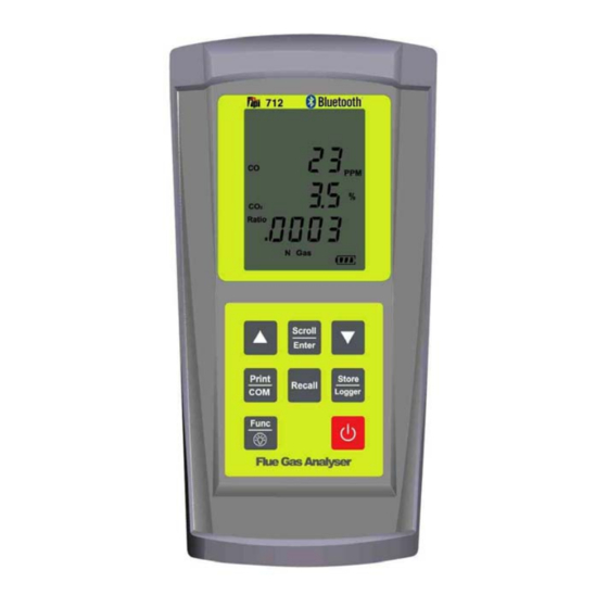
2. Instrument Overview 2.1 Front View Rubber Boot Protects the instrument from accidental damage Display Large 3 Parameter Backlit Display Battery Indicator Showing battery life Selected Fuel Type N Gas, LPG, L Oil, Heavy Oil, OPT (1~6) (See 3.1) - Page 6 Scrolls through selectable fuels (see 3.1 ) Switches between Gross and Nett Efficiency (see 4.1.2) Switches between ºC and ºF (see 4.2.1) Scrolls through mbar, kPa and inH O (see 4.3.1) Moves up through the Stored Data Addresses (see 5, 6 & 7) Increases data logging time intervals (see 8) Zeroes pressure reading (see 4.3.1) Moves down through the Stored Data Addresses (see 5, 6 &...
-
Page 7: Back View
2.2 Back View Gas and Pressure Inlet Ports Connection for In-Line Pump Protection Filter (see 2.4 & 4.4) Connections for Pressure Tubing (see 2.4 & 4.3) Calibration and Info Label Displays calibration information Displays serial number Battery Compartment Holds rechargeable battery Rubber Boot Protects the instrument from accidental damage... -
Page 8: Side Views
2.3 Side Views Exhaust Port Port for connection of Exhaust Adaptor Infrared Window Window for sending stored data to IR Printer (see 7) Rubber Boot Protects the instrument from accidental damage... -
Page 9: Top View
2.4 Top View Charger Socket Connection for 220V/115V charger (see 3.3) Thermocouple (ch1) T1 Socket Connection for thermocouple plug on probe (see 4.1) Connection for any ‘K’ type thermocouple probe (see 4.2) Thermocouple (ch2) T2 Socket Connection for any ‘K’ type thermocouple probe (see 4.2) Gas Inlet Port Connection for In-Line Pump Protection Filter for... -
Page 10: Turning On
Press the Power Key for approximately 2 seconds and the TPI 712 will start up and display ALL Segments on the display for approx. 1 second. The 712 will then enter its 30-second purge period countdown with the following screen being displayed. -
Page 11: The 5 Functions
4. THE 5 FUNCTIONS After the 30-second countdown the instrument is ready to take Flue Gas, Temperature, Pressure or Leak Detection readings and will Display the following Screen. You are now ready to take Flue Gas Analysis Readings. Please continue on with the manual from Section 4.1 (below) which will guide you through the various Analysis Screens. - Page 12 Your temperature-sampling probe comes complete with an In-Line Water Trap Bowl Filter as standard. This consists of a Particle Filter in the Bowl Compartment and a Disc Filter in the Lid (as shown in the diagram across). The Disc Filter in Lid will prevent any excessive water from entering the 712 Flue Gas Analyser if used correctly.
- Page 13 WARNING: - Ensure that the In-Line Water Trap Bowl Filter hangs in a vertical position whilst readings are being taken, particularly if water is visible (see below). Failure to comply may result in damage to the instrument and will invalidate the warranty.
- Page 14 4.1.2 HIGH CO ALARM Should the CO reading rise above 2,000ppm a continuous series of Alarm Beeps will be heard. If this occurs then the Probe should immediately be disconnected from the instrument and the instrument returned to a clean air environment. This Alarm alerts the user that there is a high concentration of CO, and this procedure will protect the sensors within the instrument.
- Page 15 4.1.5 CO Build Up Feature Whilst on Screen 3 of the Combustion Screens (see 4.1.3) press and HOLD the Store/Logger Key until the 712 beeps and the following screen is displayed:- “S-L9” will be flashing. Press the Scroll/Enter Key and choose an address location by pressing the &...
-
Page 16: Function 2: - Temperature Reading
4.1.7 Screen 5 Displays Temperature reading of Channel 1 (ch1) in degrees Centigrade (ºC) Displays Temperature reading of Channel 2 (ch2) in degrees Centigrade (ºC) Displays the Differential Temperature (Diff.) between ch1 and ch2 in ºC ‘oPEn’ will be displayed if no ‘K’ type probe is connected to the thermocouple socket 4.1.8 CO above 15ppm (Failsafe) Protection Beep The 712 will not allow the user to either Turn the instrument OFF or to move to... - Page 17 WARNING: - There is ONLY one correct way to connect the ‘K’ type thermocouple plug into the socket (see 2.4). The thermocouple plug is designed with one thick (negative) and one thinner (positive) prong. Forcing the plug into the socket the wrong way round may result in damage to the instrument.
- Page 18 4.3.1 Screen 1 Displays Pressure reading in either millibars (mbar), kiloPascals (kPa), or inches of Water (inH Pressing the Up Arrow Key will scroll through mbar, kPa and inH Pressing the Down Arrow Key will Zero the Pressure reading Pressing the Scroll/Enter Key will toggle the ch2 temperature reading ON and OFF Pressure Resolution...
- Page 19 When the Tightness Test starts the Live Pressure Reading is displayed on the top line, tItn on the middle line and the Timer on the bottom line. Once the timer reaches 1 minute it will start to flash. After the correct stabilisation period has elapsed press the Scroll/Enter Key The Start Pressure will be stored and displayed on the middle line.
-
Page 20: Function 4: - Leak Detection
Press the Scroll/Enter Key and “End YES” with “YES” flashing will be displayed. To end the Tightness Test Feature press the Scroll/Enter Key and you will be returned to Screen 1 of the Pressure Screen (see 4.3.1). However if you wish to continue and perform another Tightness Test then press the Up Arrow Key that “no”... -
Page 21: Function 5: - Date/Time
4.4.1 Screen 1 During 25 second purge period “LEAK” is displayed on the screen. It is not uncommon for the 25 second purge period to be repeated. This may happen to give the sensor sufficient time to warm up before readings can be taken. Displays and Sounds an indication to the level of Flammable Gas detected as follows: - Value on Screen... -
Page 22: Saving Data
5. SAVING DATA In addition to the CO Build Up Test & the Tightness Test it is also possible to save complete combustion readings, temperature and single pressure readings as follows:- 1. Have the 712 analyser set to the relevant screen for the readings that you wish to save (i.e. -
Page 23: Reviewing Data
6. REVIEWING DATA 1. Press the Recall Key once and the following screen will be displayed. ‘Stor’ will be flashing on the display. If you wish to review the Tightness Test Readings or the Last Time Calibrated Date then press the Down Arrow Key to have ‘tItn’... -
Page 24: Printing Data
7. PRINTING DATA WARNING: - To operate correctly there must be a clear line of sight between the Infrared Window on the instrument (see 2.3) and the Infrared Window on the IR Printer (see Printer instructions) 1. Press the Print/COM Key once and the following screen will be displayed. -
Page 25: Timed Logging
8. TIMED LOGGING Press and hold down the Store/Logger Key for approximately 2 seconds until the instrument beeps an the following screen is displayed:- ‘S-L9’ will be flashing. Press the Down Arrow Key so that ‘Lo99’ is flashing then press the Scroll/Enter Key and follow the steps below:- 1. - Page 26 2. Initiate communication with the 712BT via the relevant means on your Bluetooth enabled PC, Laptop, XDA etc…. 3. If this is the first time you have tried to connect the 712BT to your device then you must first pair the 2 devices. On your device you will be prompted to enter a Pairing Pin No.
- Page 27 Upon a successful transfer of data the 712BT will return to the original screen. “Comm” will remain flashing on the 712BT LCD. Should you wish to transfer more data to your device repeat from step 7. Should the connection between the 712BT and your device be lost then...
-
Page 28: Turning Off & Charging
10. Turning Off & Charging Always: - Before turning off the TPI 712 return to a clean air environment and allow the Carbon Monoxide level to return to below 15ppm and the Oxygen level to return to 20.9% (± 0.3%). -
Page 29: Appendix A Specifications
Appendix A : SPECIFICATIONS Instrument Operating Temperature Range -10˚C to +50˚C Battery Rechargeable Ni-MH Battery Life > 6 Hours Charger Input Voltage 115V or 230V : 50/60 Hz AC Fuels Natural Gas, LPG, Light Oil, Heavy Oil & OPT 1 = Bituminous Coal OPT 2 = Anthrachite Coal OPT 3 = Coke OPT 4 = Butane... - Page 30 Gases Range Resolution Accuracy Oxygen 0-25% 0.1% +/- 0.3% Carbon Monoxide 0-10,000 ppm 1 ppm <20 ppm : +/- 3 >100 ppm : +/- 5 % Carbon Dioxide 0-25% 0.1% +/- 0.3% (calculated) CO/CO Ratio 0-0.999 (calculated) Combustion Efficiency 0-100% 0.1% Gas Leak Sensor 100-10,000...
-
Page 31: Appendix B Calibration & Service
6 Years from the date of purchase. (Subject to annual service carried out by TPI Europe Ltd). Covered by TPI: - Repair parts and labour; or replacement of the product at the option of TPI. Normal transportation charges to the purchaser are also covered. -
Page 32: Appendix D Troubleshooting Guide
Appendix D : TROUBLESHOOTING GUIDE Problem Probable Cause Possible Remedy Unit does not turn on Batteries are flat Recharge batteries or run on mains. Unit does not turn on Dislodged battery Disconnect and Re- connect battery Continuous alarm Excessive levels of Remove probe from flue Sounds CO are being... - Page 33 Appendix E : INDEX Subject Section Alarm (CO) 4.1.2 Alarm (Failsafe) 4.1.8 Auto-Shut Off Backlight Back View Battery Charger 1 & 10.1 Battery Indicator Calibration Appendix B Charger Socket Charging 10.1 Clock 4.1.1 & Appendix A CO Build Up Test 4.1.5 4.1.1 &...
- Page 34 2.4 ; 4.1 ; 4.2 ; Appendix A & Appendix B Tightness Test 4.3.2 Top View Troubleshooting Appendix D Up Arrow Key 2.1 ; 3.1 ; 4.1.2 ; 4.2.1 ; 4.3.1 ; 4.5.1 ; 5 ; 6 ; 7 & 8 Warranty Appendix B Weight Appendix TPI Helpline 01293 530196...
- Page 36 Test products International, Ltd. 9615 SW Allen Blvd. Beaverton, OR 97005 Tel: +1 503 520 9197 Fax : +1 503 520 1225 info@tpi-thevalueleader.com www.tpi-thevalueleader.com Test products International, Ltd. 342 Bronte St. South Unit #9 Milton, Ontario L9T 5B7 Canada Tel: +1 905 693 8558 Fax: +1 905 693 0888 info@tpicanada.com...
- Page 37 Why choose the TPI 712? Balance Radiators Efficiency Analysers The “5-in-1” TPI 712 is the professional’s choice for flue gas analysis Check Thermostat & Water and is available in a number of kit formats to meet all requirements. Combustible Gas...
-
Page 38: Specifications
Longley House, International Drive Crawley, West Sussex RH10 6AQ England To learn about the entire line of TPI products visit: Tel: +44 1293 561212 Fax: +44 1293 813465 www.tpieurope.com contactus@tpieurope.com 712 Tech 14.11.06 Copyright © 2005 Test Products International Europe Ltd.
Need help?
Do you have a question about the 712BT and is the answer not in the manual?
Questions and answers