Table of Contents
Advertisement
Quick Links
Fisher Controls
R
W ARNING
To avoid injury or equipment damage, these
regulators should be installed, operated, and
maintained in accordance with federal, state
and local codes, rules and regulations, and
Fisher instructions. Only a qualified person
must install or service a regulator. Be certain the
control spring range label is updated to accu-
rately indicate any field changes in equipment,
materials, service conditions, or pressure set-
tings.
Immediately call a qualified technician in case
of trouble. If venting occurs, or a leak develops
in the system, it indicates that service is re-
quired. Failure to correct the situation immedi-
ately may create a hazardous condition.
INTRODUCTION
Scope of Manual
This manual provides installation, maintenance, and parts
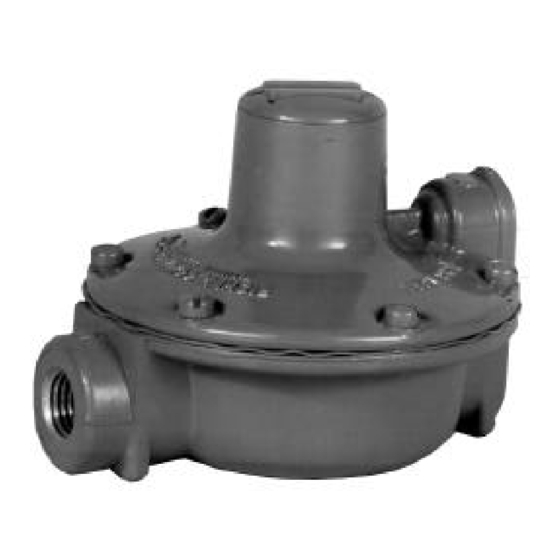
information for the 912 Series pressure regulators (figure 1)
as used in industrial/natural gas applications.
Description
The 912 Series pressure regulators are self-operated,
spring-loaded devices built to provide accurate, sensitive
control suited to a variety of applications.
As outlet pressure begins to exceed the set pressure, the
diaphragm inside the regulator lifts, operating a lever to
eFisher Controls International, Inc. 1979, 1991; All Rights Reserved
Instruction Manual
912 Series
Pressure
Regulators
May 1991
W2217
Figure 1. Type 912 Regulator
close the inlet. Pressure in excess of the relief valve spring
force opens the relief valve, allowing excess pressure to
bleed through the screened vent in the spring case.
Specifications
Specifications for the 912 Series pressure regulators are
listed in table 1.
INST ALLA TION
W ARNING
Personal injury or equipment damage may re-
sult if the regulator is installed where service
conditions could exceed the pressure or tem-
perature specifications in table 1. The regulator
must not be used for hazardous gas service in
a closed area unless the vent is piped to a safe
912 Series
Form 5124
Advertisement
Table of Contents

Subscribe to Our Youtube Channel
Related Manuals for Fisher 912 Series


Summary of Contents for Fisher 912 Series
- Page 1 1. Scope of Manual This manual provides installation, maintenance, and parts INST ALLA TION information for the 912 Series pressure regulators (figure 1) as used in industrial/natural gas applications. W ARNING Description The 912 Series pressure regulators are self-operated,...
- Page 2 Like most regulators, the 912 Series regulators have an out- be piped away. Provide protection on a remote vent by let pressure rating lower than the inlet pressure rating.
- Page 3 Key numbers are refer- W ARNING enced in figure 2. For the 912 Series constructions with no drive screw in the spring case, never adjust the con- Note trol spring to produce an outlet pressure higher...
- Page 4 Fisher Controls does not guarantee satisfactory results from reliance upon such use any product or process in conflict with any patent. Fisher Controls reserves information. the right, without notice, to alter or improve the designs or specifications of the...
Need help?
Do you have a question about the 912 Series and is the answer not in the manual?
Questions and answers