Table of Contents
Advertisement
Type 1051 & 1052 Styles H & J
Type 1051 & 1052 Styles H & J
Sizes 30, 40, 60, & 70 Rotary Actuators
Contents
. . . . . . . . . . . . . . . . . . . . . . . . . . . . . . .
. . . . . . . . . . . . . . . . . . . . . . . . . . . . .
. . . . . . . . . . . . . . . . . . . . . . . . . . . . . . . . . .
. . . . . . . . . . . . . . . . . . . . . . . . . . . . . . .
. . . . . . . . . . . . . . . . . . . . . . . . . . . . . . . .
. . . . . . . . . . . . . . . . . . . . . . . . . . .
Adjustment
. . . . . . . . . . . . . . . . . . . . . . . . . . . . . .
. . . . . . . . . . . . . . . . . . . . . . . .
. . . . . . . . . . . . . . . . . . . . . . . . . . .
. . . . . . . . . . . . . . . . . . . . . . . . . . . . .
. . . . . . . . . . . . . . . . . . . . . . . . . . . . . .
. . . . . . . . . . . . . . . . . . . . . . . . . . . . . . . . .
. . . . . . . . . . . . . . . . . . . . . . . . . . .
. . . . . . . . . . . . . . . . . . . . . . . . .
Top-Mounted Handwheels and Adjust-
able Travel Stops
. . . . . . . . . . . . . . . . . . . . . . . .
. . . . . . . . . . . . . . . . . . . . . . . . . . .
. . . . . . . . . . . . . . . . . . . . . . . . . . . . . . . . .
. . . . . . . . . . . . . . . . . . . . . . . .
. . . .
. . . . . . . . . . . . . . . .
. . . . . . . . . . . . . . . . . .
. . . . . . . . . .
. . . . . . .
. . . . .
Incorporates May 1994 Errata – See Page 38
2
2
2
3
3
3
11
11
11
13
13
14
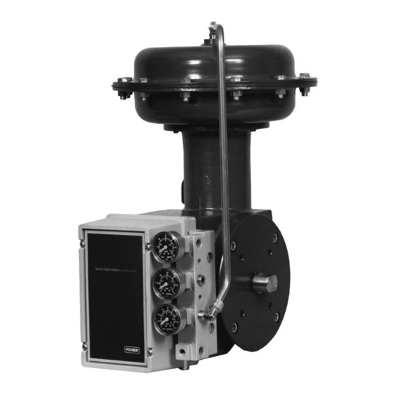
W4252/IL
Figure 1. T ype 1051 Actuator with H Mounting Adaptation and
14
14
14
16
19
19
20
21
21
21
23
W4139-1/IL
23
Figure 2. Type 1052 Actuator with J Mounting Adaptation
Instruction Manual
T ype 3610J Positioner
Form 5587
May 1990
Advertisement
Table of Contents

Related Manuals for Fisher 1051


Summary of Contents for Fisher 1051
- Page 1 ......W4252/IL Figure 1. T ype 1051 Actuator with H Mounting Adaptation and Principle of Operation T ype 3610J Positioner .
-
Page 2: Introduction
The Type cludes installation, adjustment, operation, mainte- 1051 actuator can be used for on-off service, or it can nance, and parts ordering information for the Type be used for throttling service when equipped with a 1051 (sizes 30, 40, and 60) and Type 1052 (sizes 30, valve positioner. -
Page 3: Specifications
16A3188-G Sht 2/DOC Figure 3. Nameplate Used on T ype 1051 and 1052 Actuator Specifications Specifications are shown in table 1 for Type 1051 and 1052 actuators. Specifications for a given Type 1051... - Page 4 Type 1051 & 1052 Styles H & J C0577-1/IL Figure 4. T ype 1051 Mounting Dimensions...
- Page 5 Type 1051 & 1052 Styles H & J 19A1459-B A4995/IL A3254-1/IL Figure 4. T ype 1051 Mounting Dimensions (Continued)
- Page 6 Type 1051 & 1052 Styles H & J 19A1465-B A4996/IL A3254-1/IL Figure 4. T ype 1051 Mounting Dimensions (Continued)
- Page 7 Type 1051 & 1052 Styles H & J C0678-1/IL Figure 5. T ype 1052 Mounting Dimensions...
- Page 8 Type 1051 & 1052 Styles H & J 19A1461-D A4997/IL A3252-1/IL Figure 5. T ype 1052 Mounting Dimensions (Continued)
- Page 9 Type 1051 & 1052 Styles H & J 19A1467-C A4998/IL A3252-1/IL Figure 5. T ype 1052 Mounting Dimensions (Continued)
- Page 10 Type 1051 & 1052 Styles H & J Table 4. Approximate Actuator Weights TYPE 1051 TYPE 1052 TOP-MOUNTED HANDWHEEL SIZE SIZE – – – – – – 1. For an actuator with an H mounting adaptation, attach an appropriate mounting bracket (not provided) to the mounting plate (key 22) with the cap screws (key 78).
-
Page 11: Loading Connections
Type 1051 actuator. Key numbers used in this pro- in the desired mounting position with the appropriate cedure are shown in figure 10 for Type 1051 actuators fasteners, such as mounting cap screws. - Page 12 Type 1051 & 1052 Styles H & J Table 5. Keyway Alignment Information VALVE SHAFT KEYWAY TO USE FOR FISHTAIL DISK VALVE BODIES (SEE FIGURE 8) DESIRED DESIRED DESIRED DESIRED ACTUATOR ACTUATOR COUPLING COUPLING SHAFT Clockwise to Counterclockwise to ACTUATOR...
-
Page 13: Type 1052 Spring Adjustment
Type 1051 & 1052 Styles H & J Table 6. Wrench Sizes Required for T urnbuckle Table 7. Recommended Bolting T orques Adjustment, Inches ACTUATOR SIZE TURN- LOWER UPPER ACTUATOR NUM- BUCKLE BUCKLE LOCKNUT LOCKNUT LOCKNUT LOCKNUT ft lbf ft lbf... -
Page 14: Stroking Range
Be sure the rod end bearing does not hit the figure 10 for Type 1051 actuators and in figure 11 for lever as the diaphragm and diaphragm rod move away Type 1052 actuators unless otherwise specified. - Page 15 Type 1051 & 1052 Styles H & J cator scale (key 35) must first be removed by remov- tion of the lever (key 27, figures 10 and 11) with re- ing the self-tapping screws (key 36). Mark the spect to the output shaft (key 87). This marking is...
-
Page 16: Assembly
Failure to check for step. Key numbers used are shown in figure 10 to this situation before removing the cap Type 1051 actuators and in figure 11 for Type 1052 screw (key 9) could cause personal inju- actuators. - Page 17 Type 1051 & 1052 Styles H & J CAUTION Refer to table 7 for bolting torques for actuator bolts and cap screws. Exceed- ing any torque requirement may impair the safe operation of the actuator. 2. Proceed as appropriate: For Type 1051 actuators, a.
- Page 18 Type 1051 & 1052 Styles H & J sembly into the spring barrel (key 12). After first clean- yoke (key 22) and secure it with the retaining ring (key ing and then coating the set screw (key 75) with Loc- 88).
-
Page 19: Changing Actuator Mounting
Type 1051 & 1052 Styles H & J stop. If hole alignment cannot be obtained in this man- CAUTION ner, temporarily loosen the cap screws (key 23), and shift the housing slightly. Do not stroke the actuator while the cover is off. Tighten the cap screws to the If necessary, use a wheel puller to re- torque value listed in table 7. -
Page 20: Changing Positions
Type 1051 & 1052 Styles H & J as close as possible with the hole in the rod end CAUTION bearing (key 17). If necessary, use a wheel puller to re- d. Temporarily rotate the lever and output shaft move the lever (key 27) from the output until the rod end bearing no longer interferes with shaft (key 87). -
Page 21: Top-Mounted Handwheels And Adjust Able Travel Stops
Type 1051 & 1052 Styles H & J the output shaft with the cap screw (key 28). Tight- (key 135, figure 13) against the diaphragm and dia- en the cap screw to the torque value listed in table phragm plate (keys 3 and 4, figures 10 and 11) to compress the spring (key 11, figures 10 and 11) and move the diaphragm rod downward. - Page 22 Type 1051 & 1052 Styles H & J figure 15) may need replacement or possibly the clos- c. Loosen the locknut (key 137, figure 13) or re- ing cap, (key 187, figure 15) is not tight. To tighten the move the closing cap (key 187, figure 14).
-
Page 23: Parts Ordering
Type 1051 & 1052 Styles H & J Description Part Number Qty in the introductory portion of this section, and then re- turn the unit to operation. CASING, UPPER (CONTINUED) W/HANDWHEEL, ADJ UP OR DOWN STOP SIZE 30 2E792225062 SIZE 40... - Page 24 Type 1051 & 1052 Styles H & J D0299-1/IL Figure 10. Type 1051 Actuator with Typical H and J Mounting Adaptations Description Part Number Qty Description Part Number Qty STOP, TRAVEL (CONTINUED) TYPE 1052 TYPE 1052 ONLY SIZE 30 & 40...
- Page 25 Type 1051 & 1052 Styles H & J 59A2408-B D0299-1/IL Figure 10. Type 1051 Actuator with T ypical H and J Mounting Adaptations (Continued) Description Part Number Qty SIZE 30 37A6619X012 SIZE 40 48A2485X012 Description Part Number Qty TYPE 1052...
- Page 26 Type 1051 & 1052 Styles H & J 59A2420-A D0300–1/IL Figure 1 1. Type 1052 Actuator with Typical H and J Mounting Adaptations Description Part Number Qty Description Part Number Qty NUT, HEX, JAM NUT, HEX STEEL ASTM A563GR B/ZN PL...
- Page 27 Type 1051 & 1052 Styles H & J 55A6970-J/DOC 59A2416-A/DOC 59A2420-A/DOC Figure 1 1. T ype 1052 Actuator with T ypical H and J Mounting Adaptations Description Part Number Qty Description Part Number Qty PLATE, MOUNTING, STEEL PLATE, MOUNTING, STEEL (CONTINUED) STYLE H ONLY FOR 1-3/4 INCH (44.5 mm) KEYED...
- Page 28 Type 1051 & 1052 Styles H & J 39A2401-A A3245-1/IL Figure 12. H Mounting for 1-3/4 or 2-Inch (44.5 or 50.8 mm) Keyed Equipment Shafts Description Part Number Qty Description Part Number Qty SCREW, CAP, HEX SOCKET HUB (SEE FOLLOWING TABLE)
- Page 29 Type 1051 & 1052 Styles H & J Description Part Number Qty Description Part Number Qty SCREW, CAP, HEX HD (CONTINUED) TRAVEL INDICATOR (CONTINUED) SIZES 60 & 70 1A453324052 SIZES 30 & 40 28A8534X012 W/1 OR 2 GO SWITCHES SIZES 60 & 70 28A8495X012 SIZES 30 &...
- Page 30 Type 1051 & 1052 Styles H & J Description Part Number Qty Description Part Number Qty 067* BUSHING, PTFE SCREW, CAP, HEX HD (CONTINUED) STYLE H MOUNTING ACTUATOR OUTPUT SHAFT 1A582324052 W/ 7/8-INCH (22.2 mm) W/ 2-INCH (50.4 mm) ACTUATOR OUTPUT SHAFT...
- Page 31 Type 1051 & 1052 Styles H & J Description Part Number Qty Description Part Number Qty ACTUATOR OUTPUT SHAFT (CONTINUED) 089* PIN, GROOVE, STEEL ALLOY (CONT.) SIZES 60 & 70 W/ 3/4-INCH (19.1 mm) W/ 3/4-INCH (19.1 mm) DIA 29A1876X012...
- Page 32 1N937327082 1K162827082 – – – – – – 1P270227042 10.1 1R676027082 1. For more detailed ordering information concerning proper spring selection to obtain the torque required by the valve, consult your Fisher sales office or sales representative. *Recommended spare parts...
- Page 33 32A9592x012 1. For more detailed ordering information concerning proper spring and spring seat 1-1/4 31.8 32A9576x012 selection to botain the torque required by the valve, contact your Fisher sales office 1-1/2 38.1 32A9576X012 or sales representative. Key 29 Hub, aluminum or 416 stainless steel (depending on manufacturing location) (for an actuator w/H mounting)
- Page 34 Type 1051 & 1052 Styles H & J Key 91. Woodruff Key for Actuator with H Mounting Adaptation, Alloy Steel KEYED SHAFT WOODRUFF COUPLING ACTUATOR PART NUMBER DIAMETER SIZE SIZE NUMBER NUMBER Inches 1-3/4 44.5 1211 F1358231252 60 & 70 60 &...
- Page 35 Type 1051 & 1052 Styles H & J 38A1213-B/DOC CV8010-E/DOC Figure 13. T op-Mounted Handwheel Assemblies Description Part Number Qty Description Part Number Qty PIN, COTTER, STAINLESS STEEL 140* PIN, GROOVE (CONT.) SIZES 30, 40, & 60 1B108438992 SIZE 60...
- Page 36 Type 1051 & 1052 Styles H & J 28A1207-B/DOC 28A1214-A/DOC CV8057-D/DOC Figure 14. Adjustable Up T ravel Stops...
- Page 37 Type 1051 & 1052 Styles H & J NOTE: FOR SIZE 60 ACTUATORS, A SECOND HEX NUT (KEY 54) IS USED IN THE PLACE OF THE 36A6251-B HEX NUT (KEY 63) A2951 / IL Figure 15. Adjustable Down T ravel Stop...
- Page 38 F & G Mounting Adaptation, Form 5062, October 1993 Type 1051 &1052 Styles H & J, Size 30, 40, 60, & 70 Rotary Actuators, Form 5587, May 1990 Type 1051 & 1052, Size 33, Diaphragm Rotary Actuators, Form 5620, October 1993 Type 1051 &...
Need help?
Do you have a question about the 1051 and is the answer not in the manual?
Questions and answers