Advertisement
Quick Links
Download this manual
See also:
User Manual
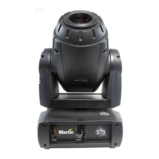
MAC 575 Krypton™ Low-Noise
Upgrade Kit Installation Guide
Introduction
This Installation Guide explains how to install the MAC 575 Krypton Low-Noise Upgrade Kit to convert a
standard MAC 575 Krypton to a Low-Noise model.
The MAC 575 Krypton Low-Noise Upgrade Kit has part number P/N 50300514.
For the latest documentation and information about this and all Martin Professional products, please visit
the Martin website at www.martin.com.
Warning! Read and follow the safety precautions in the MAC 575 Krypton user manual before installing the
Low-Noise Upgrade Kit. The user manual is supplied with the MAC 575 Krypton and is also
available for download from www.martin.com
Disconnect the fixture from power, allow to cool and place on a workbench before starting work.
The MAC 575 Krypton Low-Noise Upgrade Kit must be installed by qualified professional
technicians only. Read all of this Installation Guide carefully before starting to install the Upgrade
Kit. Martin Professional A/S and its affiliated companies cannot be held responsible for any
injury, damage, direct or indirect loss, consequential or economic loss or any other loss
resulting from failure to follow the instructions, respect the safety precautions and carry out the
safety tests listed in this Installation Guide.
If you have any questions about how to install the Upgrade Kit or use the MAC 575 Krypton
safely, please contact your local Martin distributor (see www.martin.com/distributors for details)
or call the Martin 24-hour service hotline on +45 8740 0000, or in the USA on 1-888-tech-180.
Important! To avoid damage to PCBs and their sensitive electronic components, take precautions to avoid
ESD (electrostatic discharge) and carry out work at an ESD-free workstation. Do not get oil or
grease onto optical components. If necessary, clean components with 99.9% isopropyl alcohol.
© 2008 Martin Professional A/S. Olof Palmes Allé 18, DK-8200 Aarhus N, Denmark. Information subject to change without notice. Martin
Professional A/S and all affiliated companies disclaim liability for any injury, damage, direct or indirect loss, consequential or economic
loss or any other loss occasioned by the use of, inability to use or reliance on the information contained in this installation note. The
Martin logo, the Martin name and all other trademarks in this document pertaining to services or products by Martin Professional A/S or its
affiliates and subsidiaries are trademarks owned or licensed by Martin Professional A/S or its affiliates or subsidiaries.
MAC 575 Krypton Low-Noise Upgrade Kit Installation Guide – Page 1 of 46
P/N 35000602 Rev. B
Advertisement

Related Manuals for Martin Krypton MAC 575


Summary of Contents for Martin Krypton MAC 575
- Page 1 The Martin logo, the Martin name and all other trademarks in this document pertaining to services or products by Martin Professional A/S or its affiliates and subsidiaries are trademarks owned or licensed by Martin Professional A/S or its affiliates or subsidiaries.
- Page 2 Overview The MAC 575 Krypton Low-Noise Upgrade Kit contains the following items: Table 1 MAC 575 Krypton Low-Noise Upgrade Kit Installation Guide – Page 2 of 46...
-
Page 3: Parts List
Table 1 Parts list A Wiring harness P/N 11850227 N Ballast label P/N 33160050 O Voltaflex insulation for base side cover P/N 33001113 B Wiring harness P/N 11850228 C SMPS to DC/DC PCB leads P/N 11850230 P Voltaflex insulation for pan frame P/N 33001114 D High-voltage wiring diagram P/N 33120093... -
Page 4: Schematic Wiring Diagram
Schematic wiring diagram MAC 575 Krypton Low-Noise Upgrade Kit Installation Guide – Page 4 of 46... -
Page 5: Replacement Of Components
Replacement of components To install the MAC 575 Krypton Low-Noise Upgrade Kit components in a standard MAC 575 Krypton fixture: Disconnect the fixture from power, allow to cool, and place on a workbench. Take precautions against ESD (electro-static discharge). See Figure 1. Lay the fixture on its side and remove the 14 Torx 20 pan frame retaining screws (arrowed),... - Page 6 See Figure 3. Remove the four PZ2 screws A from the base side cover on the ballast side. Keep the screws for re-use. Cut cable ties B as necessary to release the wiring to the SMPS module and move the cover away from the base.
- Page 7 See Figure 5. Cut cable ties as necessary to release the base side cover’s ground lead. Figure 5 See Figure 6. Remove the Torx 20 ground lead screw (arrowed) from the base side cover and disconnect the ground lead. Keep the screw, washer and ground lead for re-use.
- Page 8 See Figure 8. A new inner panel with air vents, P/N 23912582, is supplied in the Upgrade Kit. Turn the inner panel so that the tab (arrowed) in one edge of the inner panel is lined up with the channel in the base side side cover.
- Page 9 12. See Figure 11. Remove the Torx 20 ground lead screw (arrowed) from the end of the SMPS (switch-mode power supply). The screw, washer and ground lead are no longer required. Figure 11 13. See Figure 12. Note which terminals the voltage A and frequency B tap leads on the ballast are connected to and use a small flathead...
- Page 10 15. See Figure 14. Remove the four Torx 10 screws (arrowed, one screw is hidden behind the technician’s hand in the photo) from the DC/DC PCB mounting posts. These screws are no longer required. Move the DC/DC PCB to one side for access to the SMPS mounting screws.
- Page 11 17. See Figure 16. Lift the SMPS unit and the two PCBs out of the bracket. The bracket is no longer required, but keep the other components. Figure 16 18. See Figure 17. Disconnect the plug A with red and blue leads from connector J2 and plug B with blue and brown leads from connector J1 on...
- Page 12 19. See Figure 18. Disconnect all connectors from the DC/DC PCB. The red/blue leads and the brown/blue leads are no longer required. Remove the DC/DC PCB and keep it for re-use. Figure 18 20. See Figure 19. Disconnect the data wiring connector from connector PL1 and the light-blue and black starter (ignitor) leads shown in...
- Page 13 21. See Figure 20. Cut the cable ties on the wiring to the data connector you have just removed from the inrush PCB and pull the wiring free. Figure 20 22. See Figure 21. Using an 8 mm socket driver, remove the three M5 ballast mounting bolts and lift the ballast out of the chassis.
- Page 14 24. See Figure 23. Two new ballast mounting plates, P/N 62408400 and P/N 62408440 an M6 star washer, P/N 08114401, three new M6 ballast mounting bolts, P/N 08111007 and three flat washers, P/N 08114302, are supplied in the Upgrade Kit. On one plate there is a countersunk recess.
- Page 15 26. See Figure 25. Use a 7 mm socket to remove the nuts (arrowed) from the four screws that hold the ballast mounting brackets to the bottom of the base. You will need to hold the PZ2 screws in the base while you loosen the bolts.
- Page 16 28. See Figure 27. Disconnect the display side base fan from the top of the main PCB. Figure 27 29. See Figure 28. Disconnect the mains power leads (in a braided sleeve) from the mains filter PCB. Figure 28 30. See Figure 29. Disconnect the wiring to the DC/DC PCB from its connector (arrowed) on the bottom of the main PCB.
- Page 17 31. See Figure 30. The wiring harness that includes the main PCB-to-DC/DC PCB leads should now be free. Remove it. This wiring harness is no longer required. Figure 30 32. See Figure 31. Disconnect the SMPS side base fan at its cable connector behind where the SMPS is installed.
- Page 18 34. See Figure 33. Remove this screw from the shield plate on top of the pan frame. This screw is no longer required. Figure 33 35. See Figure 34. Remove this screw and the cable retainer mounted on it from the top of the pan frame.
- Page 19 37. See Figure 36. Remove this screw from the top of the pan frame. This screw is no longer required. Figure 36 38. See Figure 37. Remove the two screws that hold the ground leads on the top of the pan frame at both sides and lift the base top covers away from the fixture.
- Page 20 Warning! To reduce the risk of injury to yourself or damage to the fixture, two people are required for the next operation. 39. See Figure 38. While one person lifts the head and yoke assembly out of the fixture, the other person must slide the base out from underneath, leaving the...
- Page 21 42. After you have pulled wiring out of the pan frame to remove slack, the pan frame should look as shown in Figure 41. Check that all wiring is secured and that there is no slack wiring in the pan frame. Make absolutely certain that no wiring can hang under the motors (arrowed).
- Page 22 45. See Figure 41. Lower the head and yoke assembly carefully into the center of the new base so that the pan frame fits over the rigging clamp anchoring points (arrowed) and the screw holes at the edges of the pan frame line up with the screw holes in the sides of the new base.
- Page 23 47. See Figure 46. Feed the head/yoke wiring harness back into the pan frame. Turn the head to full pan left and full pan right, checking that wiring is free to move without chafing and that the head pans freely. Figure 46 48.
- Page 24 50. See Figure 49. Plug the 8-pin multi-connector on the new wiring harness into the connector (arrowed) on the bottom of the main PCB as illustrated. Figure 49 51. See Figure 50. Pass the blue and brown power lead and remaining multi-connector on the new wiring harness through the pan frame and into...
- Page 25 52. See Figure 51. Untape the leads from the fan closest to the display panel and plug them into connector F3 (arrowed) between connectors F2 and F4 on the main PCB. Figure 51 53. See Figure 52. Making sure no wiring is trapped, re-install the display/connections panel, re-using the original four PZ2...
- Page 26 54. See Figure 53. On the ballast side of the base, remove the tape you used to secure the light-blue and black starter leads and data leads and pass them out through the side of the pan frame between the two fans in the base.
- Page 27 56. If you do not need to replace the pan switch, go to step 61. on page 28. If you need to replace the pan switch, See Figure 55. Remove the two Torx 20 mounting screws (arrowed) from the existing pan switch. Keep the screws for re-use.
- Page 28 59. See Figure 58. Insert the second mounting screw in the elongated hole and.screw in until it is finger-tight only. Figure 58 60. See Figure 56. Adjust the position of the pan switch until there is approx. 2 mm clearance between the switch activation blade A and the toothed pulley B but make sure that the blade can still be...
- Page 29 62. See Figure 61. Remove the two Torx 10 screws (arrowed) from the thermosensor and let the thermosensor hang on its leads. The screws are no longer required. Figure 61 63. See Figure 62. The thermosensor leads are fastened with cable ties to the SMPS side fan leads.
- Page 30 64. See Figure 63. Attach the thermosensor leads to the ballast side fan leads, leaving approx. 10 cm (4 inches) extra length on the thermoswitch wires. Use two cable ties next to each other to reduce the strain on the leads. Figure 63 65.
- Page 31 66. See Figure 65. A new ballast mounting bracket, P/N 62408370, is supplied in the Upgrade Kit. Take the thermosensor you unfastened in step 62. and clip it onto the mounting pillars in the SMPS bracket. You may need to enlarge the holes in the thermosensor PCB slightly with a round file.
- Page 32 69. See Figure 68. Thread the thermosensor leads and ballast side fan leads that you attached in step 64. through the opening (arrowed) in the ballast mounting bracket. Figure 68 70. See Figure 69. Reconnect the thermosensor leads to the thermosensor.
- Page 33 72. See Figure 71. Secure the ballast side fan leads and thermosensor leads to the ballast mounting bracket with the cable tie (arrowed) you installed in step 67. Make sure that leads are held securely away from the fan blades. Figure 71 73.
- Page 34 75. See Figure 74. Six M4x12 Torx 20 screws, P/N 08070808, are supplied in the Upgrade Kit. Lay the fixture on its side and fasten the ballast into its bracket by tightening these six screws through the holes (arrowed) in the bottom of the base, through the ballast mounting bracket and into the ballast mounting plates.
- Page 35 78. See Figure 77. A new SMPS mounting bracket, P/N 62408380, is supplied in the Upgrade Kit. Press the DC/DC PCB onto the mounting pillars on this bracket. Figure 77 79. Two new sets of leads, both included under P/N 11850230, for the SMPS are supplied in the Upgrade Kit.
- Page 36 80. See Figure 79. Fasten the SMPS mounting bracket onto the SMPS using the two M3x8 countersunk Torx 10 screws, P/N 08050803, supplied in the Upgrade Kit. Install the cable retainer, P/N 13101010, supplied in the Upgrade Kit at Figure 79 81.
- Page 37 82. See Figure 81. Use a star washer and nut to fasten the phase correction capacitor onto the SMPS bracket. Figure 81 83. Peel off the backing paper from the bigger of the two pieces of “Voltaflex” insulating sheet, P/N 33001113, supplied in the Upgrade Kit and stick it over the center of the inner surface of the base side cover...
- Page 38 85. See Figure 84. Fasten the SMPS assembly to the flap on the ballast side cover using four new M3x6 countersunk Torx 10 screws, P/N 08050802, supplied in the Upgrade Kit. Figure 84 86. See Figure 85. Connect the double red lead from the 6-pin connector on the SMPS to the spade connector at PL 101 A on the DC/DC PCB.
- Page 39 87. See Figure 86. Connect the brown lead from the 5-pin connector on the SMPS to the spade C at PL 108 on the DC/DC PCB. Connect the blue lead from the 5-pin connector on the SMPS to the spade D at PL 105 on the DC/DC PCB Figure 86 88.
- Page 40 90. See Figure 89. Plug the 8-pin multi-connector on the wiring harness to the 8-pin socket (arrowed) on the DC/DC PCB. Figure 89 91. See Figure 90. Take the wireset included in P/N 11850228 supplied in the Upgrade Kit. Connect the blue lead’s connector A to the spade at PL 104 and connect the brown lead’s connector B...
- Page 41 92. See Figure 91. Connect the blue and black right-angled spade connectors C in Figure 90 to the spades on the phase compensation capacitor (arrowed). Polarity is not important, but the right-angled connectors must face away from each other as shown in Figure 91.
- Page 42 94. See Figure 93. Using a small flathead screwdriver, fasten the bare red lead E in Figure 90 in the voltage terminal on the ballast that matches your local mains power voltage. Figure 93 95. See Figure 94. Bend the cable retainer clip on the SMPS assembly so that it holds wires securely away...
- Page 43 98. See Figure 96. Take the ground leads from the vented side panel and the base top cover on the ballast side of the base and fasten them to the top of the pan frame re-using the screw you removed in step Figure 96 99.
- Page 44 102.See Figure 99. Install the black starter lead on the spade A at PL8. Install the blue (Neutral) starter lead on the middle spade B in the row of three spade connectors marked NEUTRAL. Install the white lead on the spade C marked BALLAST OUT next to the black connector at PL8.
-
Page 45: Safety Testing
104.See Figure 101. Re-using the original screws, install the base outer side covers and carrying handles. You have now completed the installation of components, but do not begin using the fixture until you have carried out the safety tests described in the next section. Figure 101 Safety testing Warning! The two tests described below must be carried out before the upgraded MAC 575 Krypton... -
Page 46: Product Information
The manual is also available for download from the Support area of the Martin website at http://www.martin.com. Martin Professional A/S • Olof Palmes Allé 18 • 8200 Aarhus N • Denmark Tel: +45 8740 0000 • Fax +45 8740 0010 • www.martin.com...
Need help?
Do you have a question about the Krypton MAC 575 and is the answer not in the manual?
Questions and answers