Table of Contents
Advertisement
Instruction Manual
Form 5417
February 2007
Type 1035/El-O-Matic
Rack-and-Pinion Rotary Actuator
Contents
. . . . . . . . . . . . . . . . . . . . . . . . . . . . . . .
. . . . . . . . . . . . . . . . . . . . . . . . .
. . . . . . . . . . . . . . . . . . . . . . . . . . . . . .
. . . . . . . . . . . . . . . . . . . . . . . . . . . .
. . . . . . . . . . . . . . . . . . . . . . . . . . . . . . . .
. . . . . . . . . . . . . . . . . . . . . . . . . . . . . . . . .
. . . . . . . . . . . . . . . . . . . . . . . . . . . . .
. . . . . . . . . . . . . . . . . . . . . . . . . .
. . . . . . . . . . . . . . . . . . . . . . . . . . . . .
. . . . . . . . . . . . . . . . . . . . . . .
. . . . . . . . . . . . . . . . . . . . . . . . . . . .
. . . . . . . . . . . . . . . . . . . . . . . . . . . . . . . .
. . . . . . . . . . . . . . . . . . . . . . . . . . . . . . . .
Introduction
Scope of Manual
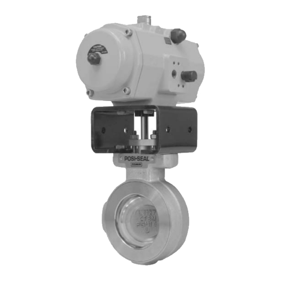
This instruction manual includes installation,
maintenance, and parts ordering information for
Type 1035/El-O-Matic rack-and-pinion rotary
actuators (figure 1). These actuators are available in
both double-acting and spring-return (figure 2)
configurations. Spring return units provide fail action
in response to spring compression. The actuator is
field reversible. Instructions for the valve and for any
accessories used with the actuator are found in
separate manuals.
Do not install, operate, or maintain a Type 1035
actuator without first D being fully trained and
qualified in valve, actuator, and accessory
installation, operation, and maintenance, and D
carefully reading and understanding the contents of
www.Fisher.com
11
11
11
. . . . . . . . . . . . . . . . . . . .
12
14
. . . . . . . . . . . . .
15
. . . . . . . . .
16
. . . . . . . . .
17
. . . . . . . . . . . . . .
18
18
19
20
1035/El-O-Matic Actuator
1
1
2
2
4
5
W9255
Figure 1. Type 1035/El-O-Matic Actuator
this manual. If you have any questions about these
instructions, contact your Emerson Process
Managementt sales office before proceeding.
Neither Emerson, Emerson Process
Management, nor any of their affiliated
entities assumes responsibility for the
selection, use and maintenance of any
product. Responsibility for the
selection, use, and maintenance of any
product remains with the purchaser
and end-user.
with Type A41 Valve
Note
Advertisement
Table of Contents

Related Manuals for Fisher D500243X012


Summary of Contents for Fisher D500243X012
-
Page 1: Table Of Contents
D carefully reading and understanding the contents of www.Fisher.com 1035/El-O-Matic Actuator ..... . -
Page 2: Description
1035/El-O-Matic Actuator Type 1035 Actuator: Double Acting EDA 25 EDA 40 EDA 65 EDA 100 EDA 200 EDA 350 EDA 600 EDA 950 EDA 1600 PDA 2500 PDA 4000 Output Shaft: J Double D insert for Type A41 valves J Optional ISO 5211 square insert, Recessed ISO 5211 square drive for P Series actuators Dual Stop Adjustment: J E Series actuators are... - Page 3 Instruction Manual Form 5417 February 2007 BORE E SERIES ACTUATOR ACTUATOR SIZE Inch E100 E200 E350 E600 E950 E1600 P2500/P2505 11.8 P4000/P4005 12.8 1. These times assume smaller solenoids for smaller actuators and larger solenoids for larger actuators with varying Cvs, but a constant air supply pressure of 80 psi (5.51 bar). E25 to E350 assume a 0.09 Cv (0.08 Kv);...
-
Page 4: Installation
1035/El-O-Matic Actuator Table 3. Approximate Weights ACTUATOR ACTUATOR SIZE E100 E200 E350 10.4 16.9 E600 19.4 27.6 E900 26.4 38.6 E1600 42.7 65.8 P2500/P2505 56.7 88.0 P4000/P4005 86.2 132.0 Table 4. Bolting Torques between 1035 and Yoke ACTUATOR Bolt Diameter, Torque, NSm SIZE Inches... -
Page 5: Operation
Instruction Manual Form 5417 February 2007 be used to mount the actuator to the yoke/mounting actuator. WARNING Exceeding any torque requirement may impair the safe operation of this actuator by causing broken or damaged parts. Refer to table 4 for bolting torque requirements. - Page 6 1035/El-O-Matic Actuator ACTUATOR DRIVE SHAFT DOUBLE-D AND PINION GEAR POSITION END CAP TRAVEL HOUSING TRAVEL STOP ADJUSTS STOP ADJUSTS OPEN POSITION CLOSED POSITION PISTONS INSTALLED 180_ PIPELINE FROM STANDARD CODE A END CAP TRAVEL STOP ADJUSTS CLOSED POSITION (BOTH ENDS) NOTES: DRAWING SHOWS THE ORIENTATION OF THE DOUBLE-D VALVE CONNECTION ON THE SHAFT WITH RESPECT TO THE SLOT IN THE TOP OF THE DRIVE SHAFT.
- Page 7 Instruction Manual Form 5417 February 2007 DOUBLE-D ACTUATOR DRIVE SHAFT POSITION AND PINION GEAR HOUSING TRAVEL STOP ADJUSTS CLOSED POSITION PISTONS INSTALLED 180_ FROM STANDARD CODE A PIPELINE END CAP TRAVEL STOP ADJUSTS CLOSED POSITION (BOTH ENDS) NOTES: DRAWING SHOWS THE ORIENTATION OF THE DOUBLE-D VALVE CONNECTION ON THE SHAFT WITH RESPECT TO THE SLOT IN THE TOP OF THE DRIVE SHAFT.
- Page 8 1035/El-O-Matic Actuator SQUARE ACTUATOR DRIVE SHAFT INSERT AND PINION GEAR PISTONS INSTALLED 180_ FROM STANDARD CODE A PIPELINE NOTES: DRAWING SHOWS THE ORIENTATION OF THE SQUARE INSERT VALVE CONNECTION ON THE SHAFT WITH RESPECT TO THE SLOT IN THE TOP OF THE DRIVE SHAFT. 75B0452 A7045 / IL Figure 3.
- Page 9 Instruction Manual Form 5417 February 2007 ACTUATOR DRIVE SHAFT SQUARE AND PINION GEAR INSERT PISTONS INSTALLED 180_ FROM STANDARD CODE A PIPELINE NOTES: DRAWING SHOWS THE ORIENTATION OF THE SQUARE INSERT VALVE CONNECTION ON THE SHAFT WITH RESPECT TO THE SLOT IN THE TOP OF THE DRIVE SHAFT. 75B0443 A7046 / IL Figure 3.
- Page 10 1035/El-O-Matic Actuator LIMIT STOP PLATE STOP ADJUSTMENT 1 ELO A 1.501.05 5/96 ELO A 1.503.05 5/96 A6952-1 / IL LOCK NUT HOUSING ADJUSTMENT OPEN 3_ 10_ ADJUSTABLE RANGE STOP PLATE STOP ADJUSTMENT 2 LOCKNUTS MOUNTING BRACKET Figure 4. Travel Stop Adjustments Instruction Manual Form 5417 February 2007...
-
Page 11: Adjustment
Instruction Manual Form 5417 February 2007 A7047 / IL Troubleshooting If the actuator does not function, make the following checks: 1. Check for worn teeth on piston racks, if the actuator exhibits excessive amounts of backlash. If worn, replace piston/gear rack assembly. 2. -
Page 12: Actuator Disassembly
1035/El-O-Matic Actuator any maintenance operations to avoid personal injury. D The valve packing area may contain process fluids that are pressurized, even when the valve has been removed from the pipeline. Process fluids may spray out under pressure when removing the packing hardware or packing rings. - Page 13 Instruction Manual Form 5417 February 2007 PISTON (KEY 2) NOTE: THE PISTON IS SHOWN IN THE FULLY RETRACTED POSITION. SPRINGS ARE FULLY EXTENDED AND CONTAINED WITHIN THE SPRING HOLDER BY THE WASHER (KEYS 9 AND 34). THE WASHER KEEPS THE SPRING RETAINER CONNECTED TO THE END CAP. ELO A4.204.03 A7038 / IL Figure 6.
-
Page 14: Actuator Assembly
1035/El-O-Matic Actuator 4. Remove the adjustable travel stop/ housing adjustment (see figure 4). 5. Removing the Pistons: The two pistons (key 2) can now be removed by rotating the drive shaft, moving the piston assemblies outward until the pinion gear has released them. The gear rack in E Series actuators is machined into the piston, and so does not have to be removed separately. -
Page 15: Changing Rotation Direction
Instruction Manual Form 5417 February 2007 construction does not use the adjustment screw, install the drive shaft, and go to step 6 below. 5. Note the alignment of the cam with respect to the housing adjustment screw while installing the shaft into the body. -
Page 16: Spring Return E Series Actuators
1035/El-O-Matic Actuator NOTE: PISTONS ARE SHOWN IN THE CODE A POSITION 75B0509-A A7042 / IL SPRING SET 2 MID SPRING ELO A 4.202 A7040 / IL Spring Return E Series Actuators Spring return E Series actuators use from two to a maximum of six springs. -
Page 17: Spring Return P Series Actuators
Instruction Manual Form 5417 February 2007 8 SPRINGS 12 SPRINGS ELO A 4.201 A7041-1 / IL Figure 9. Spring Arrangement for P Series Actuators 4. Place the end cap bolts through the retention holes of the end cap. If converting a double acting unit to a spring return unit, be sure to use new end cap screws (key 25, figure 12). -
Page 18: Installing The Bypass Valve
Use only genuine Fisherr replacement parts. Components that are not supplied by Emerson Process Management should not, under any circumstances, be used in any Fisher valve, because they will void your warranty, might adversely affect the performance of the valve, and could give rise to personal injury and property damage. -
Page 19: Parts Kits
Instruction Manual Form 5417 February 2007 Parts Kits Actuator E100 E200 E350 E600 E950 E1600 P2500/P2505 P4000/P4005 Actuator E100 E200 E350 E600 E950 E1600 P2500/P2505 P4000/P4005 Table 5. Repair Kits Standard Construction High Temperature Nitrile O-Rings Fluorocarbon O-Rings 75B0594X012 75B0595X012 75B0594X022 75B0595X022 75B0594X032... -
Page 20: Parts Reference
1035/El-O-Matic Actuator Parts Reference Table 7. E Series Parts List Key Number Description Body, If you need an actuator body (key 1) as a replacement part , order by actuator size, serial number, and desired material. Contact your Emerson sales office. Piston, Aluminum alloy Drive shaft, Aluminum End cap (EDN), Aluminum alloy... - Page 21 Instruction Manual Form 5417 February 2007 NOTE: PARTS NOT SHOWN ARE HOUSING ADJUSTMENT SCREW, HEX (LOCK) NUT AND STROKING CAM. REFER TO FIGURE 4 FOR LOCATION OF PARTS. ELO A 1.101.33 (3-96) 1035/El-O-Matic Actuator OPTIONAL CENTER-PLATE Figure 11. Type 1035 E Series Actuator Assembly...
- Page 22 Instruction Manual Form 5417 1035/El-O-Matic Actuator February 2007 A 1.101.30 (3-96) Figure 12. Type 1035 P Series Actuator Assembly...
- Page 23 Instruction Manual Form 5417 1035/El-O-Matic Actuator February 2007...
- Page 24 February 2007 Fisher is a mark owned by Fisher Controls International LLC, a member of the Emerson Process Management business division of Emerson Electric Co. Emerson Process Management, Emerson, and the Emerson logo are trademarks and service marks of Emerson Electric Co.
Need help?
Do you have a question about the D500243X012 and is the answer not in the manual?
Questions and answers