Advertisement
Quick Links
Instruction Manual
Form 5084
July 2011
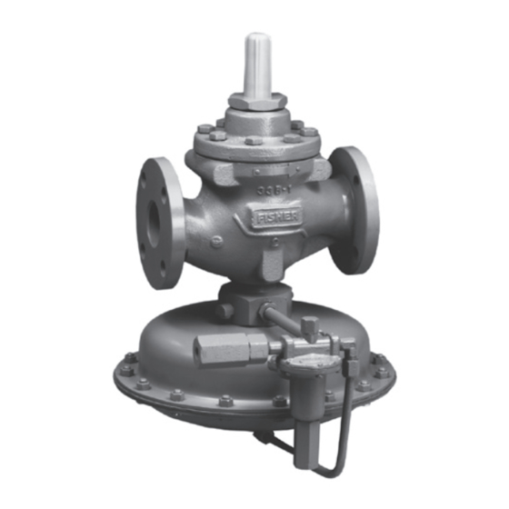
Types 1098-EgR and 1098H-EgR Pressure
Reducing Regulators
wARNINg
!
Failure to follow these instructions or
to properly install and maintain this
equipment could result in an explosion,
fi re and/or chemical contamination
causing property damage and personal
injury or death.
Fisher
regulators must be installed,
®
operated, and maintained in accordance
with federal, state, and local codes, rules
and regulations, and Emerson Process
Management Regulator Technologies, Inc.
(Regulator Technologies) instructions.
If the regulator vents gas or a leak
develops in the system, service to the unit
may be required. Failure to correct trouble
could result in a hazardous condition.
Installation, operation, and maintenance
procedures performed by unqualifi ed
personnel may result in improper
adjustment and unsafe operation. Either
condition may result in equipment
damage or personal injury. use qualifi ed
personnel when installing, operating,
and maintaining the Types 1098-EgR and
1098H-EgR pressure reducing regulator.
Introduction
Scope of the Manual
This manual describes and provides instructions and
parts list for Type 1098-EGR or Type 1098H-EGR
regulator complete with a standard P590 Series
fi lter and either a 6350 Series regulator, a 61 Series
pilot, or a Type Y600AM pilot. The Type 1806 relief
Types 1098-EGR and 1098H-EGR
W6956
valve is also covered when a 61 Series pilot is used.
Instructions and parts lists for monitoring pilots and
other equipment used with this regulator are found in
separate manuals.
Description
Types 1098-EGR and 1098H-EGR regulators provide
economical and accurate pressure control in a
wide variety of applications: natural gas distribution
systems; fuel gas supply to industrial boilers, furnaces,
ovens, and mixers; and large commercial/industrial
establishments such as shopping centers and schools.
They are also used in plant air service and in liquid
service where a slow stroking time (approximately
30 to 90 seconds) is desired on both opening and
closing the main valve.
www.fi sherregulators.com
Figure 1. Type 1098-EGR
Advertisement

Related Manuals for Fisher 1098H-EGR


Summary of Contents for Fisher 1098H-EGR
- Page 1 This manual describes and provides instructions and establishments such as shopping centers and schools. parts list for Type 1098-EGR or Type 1098H-EGR They are also used in plant air service and in liquid regulator complete with a standard P590 Series...
-
Page 2: Specifications
The Specifications section lists pressure limitations and other specifications for various Types 1098-EGR and 1098H-EGR constructions. Specifications for a given regulator as it originally comes from the factory are stamped on nameplates located on both the actuator and main valve body, while the pilot control spring range is displayed on the pilot spring case, and the pilot restriction code is stamped on the pilot body (S = standard gain, L = low gain, and H = high gain). - Page 3 Types 1098-EGR and 1098H-EGR Table 2. Outlet Pressure Ranges OuTlET PRESSuRE RANgE PIlOT TyPE SPRINg COlOR SPRINg PART NuMBER psig 3 to 20 0,21 to 1,4 Green 1B986027212 6351 5 to 35 0,35 to 2,4 Unpainted 1B788327022 35 to 100...
-
Page 4: Principle Of Operation
Principle of Operation Reduced actuator loading pressure permits the main valve to close. The combination of main valve spring The pilot-operated Types 1098-EGR and 1098H-EGR force and valve plug imbalance provides positive valve regulators both use inlet pressure as the operating plug shutoff against the port and upper seals. - Page 5 Types 1098-EGR and 1098H-EGR TyPE 6351 TyPE 1098-EgR TyPE 6352, 6353, OR 6354 TyPE 1098-EgR wITH 6350 SERIES PIlOT A6563 INlET PRESSuRE OuTlET PRESSuRE ATMOSPHERIC PRESSuRE lOADINg PRESSuRE TyPE 1098-EgR TyPE 1806 TyPE 61lD TyPE 1098-EgR wITH TyPE 61lD PIlOT AND TyPE 1806 RElIEF VAlVE...
-
Page 6: Installation And Startup
Installations given in the Specifications section and on the appropriate nameplate, or where A Type 1098-EGR or Type 1098H-EGR regulator conditions exceed any ratings of the bleeds no gas to the atmosphere, making it suitable for adjacent piping or piping connections. - Page 7 1/2-INCH / 13 mm PIPE PIlOT SuPPly lINE 1/2-INCH / 13 mm PIPE FIlTER VENT TyPE 1098-EgR OR 1098H-EgR REgulATOR wITH STANDARD 6350 SERIES PIlOT 48A6566-A B1622 Figure 3. Standard Single-Pilot Installation TO PIlOT PIlOT lIgHT SuPPly lINE 1/2-INCH / 13 mm PIPE...
- Page 8 Types 1098-EGR and 1098H-EGR Note 3. To keep the pilot spring case vent from being plugged or the spring case from collecting Normal pressure drop assists shutoff. moisture, corrosive chemicals, or other foreign Therefore, leakage may result during any material, point the vent down or otherwise protect reverse pressure drop condition.
- Page 9 Type 1098-EGR boiler fuel configuration: The only adjustment necessary on a Type 1098-EGR • Type 1098-EGR with Type 6352 pilot or 1098H-EGR regulator is the pressure setting of • Size 70 Actuator the pilot control spring. Turning the adjusting screw •...
- Page 10 Types 1098-EGR and 1098H-EGR TyPE 1098-EgR SIzE 70 wITH quICK OPENINg CAgE 20 psi / 1,4 bar MAxIMuM SAFTEy SHuT-OFF VAlVE SuPPly TO BOIlER FAST-ACTINg TyPE lOAD VAlVE 1098-EgR PIlOT SuPPly TyPE 6352 wORKINg PIlOT PIlOT gAS TO PIlOT lIgHT...
-
Page 11: Second-Stage Regulator
Table 6 shows how close the standby pilot can be pressure lower than the Type 1098-EGR or 1098H-EGR set to the working pilot setting. working monitor regulator. To do this, increase the setting 4. - Page 12 Types 1098-EGR and 1098H-EGR Table 6. Auxiliary Pilot Selection (Fast Stroke Dual Pilot) MINIMuM PRESSuRE ORIFICE SPRINg RANgE SPRINg SPRINg SIzE CONSTRuCTION AT wHICH AuxIlIARy NuMBER COlOR Inches PIlOT CAN BE SET 4 to 8-inches w.c. 10 to 20 mbar 1B653827052 1-inch w.c.
- Page 13 Types 1098-EGR and 1098H-EGR 16A4296-A 16A4297-A FlExIBlE wIDE-OPEN MONITOR ARRANgEMENT THAT PERMITS MINIMuM PIPINg wIDE-OPEN MONITOR ARRANgEMENT THAT wIDE-OPEN MONITOR TO BE EITHER uPSTREAM OR DOwNSTREAM REquIRES wIDE-OPEN MONITOR AlwAyS TO BE uPSTREAM PIlOT SuPPly REgulATOR Figure 8. Typical Wide-Open Monitor Installations 2.
-
Page 14: Maintenance
Types 1098-EGR and 1098H-EGR BODy FlANgE CAgE SCREwS INTO SEAT RINg BODy FlANgE SCREwS INTO CAgE W3012-1* W2772-1 Figure 9. Trim Package Removal Figure 10. Seat Ring / Cage Removal or Installation Using Body as Holding Fixture Shutdown working Monitor 1. - Page 15 All disassembly, trim change, and 10C1212 reassembly steps in this section may be performed with the regulator in the main Figure 11. Types 1098-EGR and 1098H-EGR Travel line and without disconnecting the pilot Indicator Assembly supply or control lines. 1. Remove the cap screws (key 3) with a cast iron 4.
- Page 16 Types 1098-EGR and 1098H-EGR 2. Remove the cap screws (key 3) on a cast iron Type EGR Main Valve Cap Screw (key 3) Torque body or remove the hex nuts (key 29, not shown) on a steel body, and pry the body flange (key 2)
- Page 17 Types 1098-EGR and 1098H-EGR P590 Series Filter seat ring (key 13) plus port seal (key 12) into the cage. Apply a thin coating of lubricant to seals Perform this procedure to clean or replace filter parts in a for protection during assembly. Use the valve standard Type P593-1 or P594-1 filter assembly.
- Page 18 Types 1098-EGR and 1098H-EGR 61 Series Pilot and Type 1806 Relief Valve Type 6351 pilots manufactured before May 1999 need to have the body plug gasket and the body Perform this procedure if changing the control spring plug replaced with a new body plug assembly...
- Page 19 Types 1098-EGR and 1098H-EGR a. Before replacing the diaphragm case (key 2) 3. Inspect and replace the orifice (key 5) if or spring case (key 1), be sure the yoke assembly necessary. Protect the orifice seating surface is positioned so that it will not bind or rub on the during disassembly and assembly.
- Page 20 Types 1098-EGR and 1098H-EGR 4. To replace the lever assembly (key 16), remove 1. Unscrew the valve plug guide (key 5) from the the machine screws (key 17). To replace the body (key 1). The valve plug spring (key 10) and...
-
Page 21: Parts Ordering
(key 12) from the diaphragm plate (key 8), remove Parts Ordering the stem cap screw (key 9). Each Type 1098-EGR or 1098H-EGR regulator is 4. To remove the Type 1098 case O-ring assigned a serial number or FS number which can be (key 5), unscrew the four case cap screws found on the nameplates. - Page 22 Types 1098-EGR and 1098H-EGR Type EgR Main Valve (Figures 12 and 13) Description Part Number Description Part Number Elastomer Trim Parts kit (included are: Cast Iron Body Flange (continued) keys 4, 7, 12, 14, 15, 17, 20, 21, 36, and 37)
-
Page 23: End Connection
Types 1098-EGR and 1098H-EGR Key 1 Type EGR Main Valve Bodies MATERIAl END CONNECTION NPS 1 / DN 25 NPS 2 / DN 50 34B7611X012 38A8845X012 Cast Iron CL125 FF 34B8630X012 38A8847X012 CL250 RF 37B5950X012 38A8846X012 37B5946X012 38A8848X012 CL150 RF... - Page 24 Types 1098-EGR and 1098H-EGR Type EgR Main Valve (Figures 12 and 13) (continued) Description Part Number Description Part Number Travel Indicator Stem (continued) Stud Bolt, Stainless steel (use with Stainless steel body) 316 Stainless steel (NACE) (not shown) NPS 1 / DN 25...
- Page 25 Types 1098-EGR and 1098H-EGR INDICATOR Plug ASSEMBly 35A3167 COMPlETE CAST IRON Full-CAPACITy MAIN VAlVE ASSEMBly Figure 12. Type EGR Main Valve Construction...
- Page 26 Types 1098-EGR and 1098H-EGR 26A3800 DETAIl OF OPTIONAl RESTRICTED CAPACITy CONSTRuCTION quICK-CHANgE TRIM PACKAgE ASSEMBly 25A3170 Figure 13. Type EGR Main Valve Internal Constructions Type EgR Main Valve (Figures 12 and 13) (continued) Description Part Number Description Part Number Seat Ring...
- Page 27 Types 1098-EGR and 1098H-EGR Type EgR Main Valve (Figures 12 and 13) (continued) Description Part Number Description Part Number 15* Upper Seal Travel Indicator Scale, plastic Nitrile (NBR) (standard) NPS 1 / DN 25 14A6759X012 NPS 1 / DN 25...
- Page 28 Types 1098-EGR and 1098H-EGR Type EgR Main Valve Types 1098 and 1098H Actuators (Figures 12 and 13) (continued) (Figure 14) Description Part Number Description Part Number Indicator Plug Lower Casing Zinc-plated steel Size 30 NPS 1 / DN 25 14A6983X012...
- Page 29 Types 1098-EGR and 1098H-EGR 56 12 11 10 34A5692 TyPE 1098 29 13 36A8540 TyPE 1098H Figure 14. Types 1098 and 1098H Actuator Assemblies...
- Page 30 Types 1098-EGR and 1098H-EGR Types 1098 and 1098H Actuators (Figure 14) (continued) Description Part Number Description Part Number Nameplate - - - - - - - - - - - Diaphragm (continued) Vent Insert Type Y602-12 Type 1098H Zerk Fitting, plated carbon steel...
- Page 31 Types 1098-EGR and 1098H-EGR AJ5004 Figure 15. Standard P590 Series Filter Assembly 34A5853 APPly SEAlANT (S) S = MulTI-PuRPOSE PTFE THREAD SEAlANT Figure 16. Type 6351 Pilot Assembly...
- Page 32 Types 1098-EGR and 1098H-EGR Type 6351 Pilot (Figure 16) (continued) Description Part Number Description Part Number Diaphragm Assembly Body Plug (includes plated steel diaphragm plate) Aluminum 15A6221X012 Nitrile (NBR) diaphragm and 316 Stainless steel 15A6221X042 Aluminum pusher post 1B7980000B2 Valve Plug and Stem Assembly...
- Page 33 Types 1098-EGR and 1098H-EGR 35A8889 35A6236 DETAIl OF TyPE 6354M OR 6354H PIlOT TyPE 6352, 6353, OR 6354l PIlOT Figure 17. Types 6352 through 6354H Pilot Assemblies 20A6328 DETAIl OF CAPPED ADjuSTINg SCREw OPTION 20A6326 30A6327 TyPES 61l, 61lD, AND 61lE PIlOT DETAIl OF HANDwHEEl OPTION Figure 18.
- Page 34 Types 1098-EGR and 1098H-EGR Types 6352, 6353, 6354l, 6354M, and 6354H Pilots (Figure 17) (continued) Description Part Number Description Part Number Machine Screw (6 required) Relay Valve Body, Cast Iron Aluminum 10B6189X022 Types 61L, 61LD, 61LE, and 61H 2J581919012 Stainless steel...
- Page 35 Types 1098-EGR and 1098H-EGR 30A6330 DETAIl OF CAPPED ADjuSTINg SCREw OPTION 32A2068 TyPE 61H PIlOT APPly SEAlANT (S) S = MulTI-PuRPOSE PTFE THREAD SEAlANT Figure 19. Type 61H Pilot Assembly 34A0396 Figure 20. Type 61HP Pilot Assembly...
- Page 36 Types 1098-EGR and 1098H-EGR 61 Series Pilots (Figures 18, 19, and 20) (continued) Description Part Number Description Part Number Cap Screw (8 required), Zinc-plated steel Bleed Orifice, 303 Stainless steel (For 61 Series except Type 61HP) 1B989624052 Types 61L, 61LD, 61LE, and 61H...
- Page 37 Types 1098-EGR and 1098H-EGR 47B3687 47B3687 APPly luBRICANT (l) l1 = SIlICONE gREASE luBRICANT l2 = ANTI-SEIzE AND luBRICATINg COMPOuND Figure 21. Type Y600AM Regulator Assembly Figure 22. Diaphragm Casing Cap Screw Location Type y600AM Parts list (Figures 21 through 22)
- Page 38 Types 1098-EGR and 1098H-EGR 30A7022 APPly ANTI-SEIzE COMPOuND (l2) Figure 23. Type 95H Supply Pressure Regulator Type 95H Regulator (Figure 23) Description Part Number Description Part Number Parts Kit (Included are keys 3, 4, 10, and 12) Lower Spring Seat...
- Page 39 Types 1098-EGR and 1098H-EGR CONTROl lINE CONNECTION BOTTOM VIEw OF PIlOT (SHOwN ROTATED 90° FROM NORMAl) 14A5706-A Figure 24. Single-Pilot Mounting Assembly Mounting Parts 6350 Series Mounting Parts (Figure 24) Description Part Number Description Part Number Pipe Tee for use with 50 psig / 3,4 bar relief...
- Page 40 Types 1098-EGR and 1098H-EGR CONTROl lINE CONNECTION 14A5705 Figure 25. 61 Series Pilot and Type 1806 Relief Valve Mounting Mounting Parts (continued) 61 Series Mounting Parts (Figure 25) Description Part Number Description Part Number Pipe Nipple Loading Tubing For standard 61 Series mounting...
- Page 41 Types 1098-EGR and 1098H-EGR 37A0565 Figure 26. Working Monitor Assembly Auxiliary Pilot Mounting Parts (Figure 26) Description Part Number Description Part Number Tube Elbow - - - - - - - - - - - Flared Nut (1 required for use with...
- Page 42 Types 1098-EGR and 1098H-EGR TyPE 95H SuPPly PRESSuRE REgulATOR TyPE y600AM PIlOT 42B6644 OPTIONAl: TyPE 112 RESTRICTOR Figure 27. Type 1098-EGR with Type Y600AM Mounting Parts Mounting Parts (continued) Type 1098-EGR with Type Y600AM Mounting Parts (Figure 27) Description Part Number...
- Page 43 Types 1098-EGR and 1098H-EGR VIEw A-A VIEw B-B SuPPly TyPE y600AM 6350 SERIES VENT CONTROl 47A7118 TyPE y600AM AND SIzE 70 TyPE 1098 COMBINATION SuPPly VIEw A-A VIEw B-B TyPE 621-107 6350 SERIES CONTROl 47A7119 TyPE 627M AND SIzE 70 TyPE 1098 COMBINATION APPly SEAlANT (S) All NPT THREAD Figure 28.
- Page 44 For further information visit www.fisherregulators.com The Emerson logo is a trademark and service mark of Emerson Electric Co. All other marks are the property of their prospective owners. Fisher is a mark owned by Fisher Controls, Inc., a business of Emerson Process Management.
Need help?
Do you have a question about the 1098H-EGR and is the answer not in the manual?
Questions and answers