Table of Contents
Advertisement
Quick Links
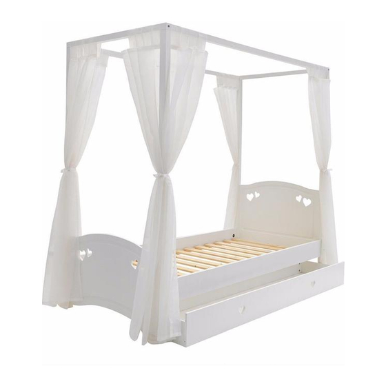
Mia 4 Poster Bed
Dimensions
:
Width
197.3 cm
Depth
:
99.5 cm
:
186.2 cm
Height
Assembly Instructions -
If you need help or have damaged or missing parts, call the Argos Customer Helpline: 0845 640 30 30
350268-01
Please keep for future reference
Please keep for future reference
White 2627436
Pink 2557386
Issue 1 - 26-05-2014
Advertisement
Table of Contents

Subscribe to Our Youtube Channel
Summary of Contents for Argos Mia 2627436
- Page 1 197.3 cm Depth 99.5 cm 186.2 cm Height Assembly Instructions - Please keep for future reference If you need help or have damaged or missing parts, call the Argos Customer Helpline: 0845 640 30 30 Issue 1 - 26-05-2014 350268-01...
- Page 2 ! Safety and Care Advice Important - Please read these instructions fully before starting assembly • Check you have all the • Do not stand or put weight on components and tools listed on the product, this could cause pages 2 and 3. damage.
- Page 3 Components - Panels If you have damaged or missing components, call the Argos Customer Helpline: 0845 640 30 30 Please check you have all the panels listed below Post, headboard (182,4 cm x 5 cm) Post, foot (182,4 cm x 5 cm)
- Page 4 Components - Fittings Please check you have all the panels listed below Note: The quantities below are the correct amount to complete the assembly. In some cases more fittings may be supplied than are required. ø7.8 x 40mm Wooden dowel x ø3 x 12mm Screw x ø3,5 x 30mm Screw x ø15 x 10.5mm Cam x 12...
- Page 5 Assembly Instructions Step 1 Assembly of the bed. Step 1.1 Knock the dowels into ø7.8 x 40mm Wooden dowel x the holes indicated on the side rails using a small hammer. Step 1.2 Screw the bushings into M6 x 20mm Bushing x 4 Allen key x the holes indicated on the posts...
- Page 6 Assembly Instructions Step 1.3 Fix the posts onto the M6 x 80mm Bolt x 8 M6, ø10 x 12.5mm barrel nut x 8 headboard using bolts into the barrel nuts Note - the holes in the posts for the siderails must point Allen key x downwards.
- Page 7 Assembly Instructions Step 1.4 Screw the threaded rods ø3 x 12mm Screw x M6 x 70mm Threaded rod x 4 into the bushings the posts Fix the angles to the Angle 23 x 23 x 24mm x 4 posts using screws into the holes indicated.
- Page 8 Assembly Instructions Step 1.5 Place the side rails ø35mm Bracket x 2 M6 x 10mm Nut x 2 onto the headboard posts Push the brackets 10/13mm Wrench x 1 the nuts into the holes indicated on the side rails and onto the threaded rods Tighten the nuts using...
- Page 9 Assembly Instructions Step 1.6 Place the footboard posts ø35mm Cap x ø35mm Bracket x 2 onto the side rails Push the brackets the nuts into the holes M6 x 10mm Nut x 2 10/13mm Wrench x 1 indicated on the side rails and onto the threaded rods Tighten the nuts...
- Page 10 Assembly Instructions Step 1.7 Fix the top rails (side) M6 x 80mm Bolt x 4 M6, ø10 x 12.5mm barrel nut x 4 the toprails (end) using bolts into the barrel nuts Allen key x Use the allen key Step 1.8 Fix the corner angles ø3 x 12mm Screw x 70 x 70 x 16mm Corner angle x 4...
- Page 11 Assembly Instructions Step 1.9 Place the top frame on the ø3 x 12mm Screw x top of the posts. Fix it using screws through the angles 350268-11...
- Page 12 Assembly Instructions Step 1.10 Fix the first of the slats ø3,5 x 30mm Screw x to the slatholders using screws The slats must be distributed evenly in the bedframe. To get the distance right use the spacer block as shown. See detail.
- Page 13 Assembly Instructions Step 1.12 Fix the rest of the slats ø3,5 x 30mm Screw x using screws To get the distance right use the spacer block shown. See detail. 350268-13...
- Page 14 Assembly Instructions Step 2 Assembly of the drawer. Step 2.1 Screw the bolts into ø7.8 x 40mm Wooden dowel x ø5 x 8, cc34mm Bolt x 6 the holes indicated on the drawer back and the drawer sides Knock the dowels into the holes indicated on the drawer back...
- Page 15 Assembly Instructions Step 2.3 Screw the bolts into ø5 x 8, cc34mm Bolt x 6 the holes indicated on the drawer front Step 2.4 Push the drawer sides ø15 x 10.5mm Cam x 6 and the drawer rails onto the drawer back Place cams into the...
- Page 16 Assembly Instructions Step 2.6 Push the drawer front ø15 x 10.5mm Cam x 6 onto the drawer sides and the drawer rails Place cams into the holes indicated. Arrow pointing towards the front. Turn the cams to the right to fix the front. Step 2.7 Place the drawer.


Need help?
Do you have a question about the Mia 2627436 and is the answer not in the manual?
Questions and answers