Advertisement
Quick Links
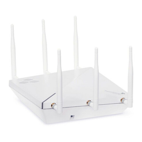
Aerohive QuickStart for the AP370 and AP390
This guide explains how to install an Aerohive AP370 or AP390 access point so it can make a network
connection to HiveManager. The instructions in this document apply to both models. To register, get
the latest product documentation, (including translations of select documents), see compliance
information, and download software updates, visit www.aerohive.com/support.
AP370 Kit Contents
• AP370 device with USB
slot cover installed
• 2 security screws
• 2 slotted screws
• 1 security bracket
• QuickStart Guide
Connecting the Device
For AP390 models, attach external antennas
AP370
to the 5 GHz and 2.4 GHz connectors.
ETH0
1
DHCP
server
Connect a standard
Switch
RJ45 Ethernet cable
Ethernet
Some other network devices (They
from ETH0 on the AP to
cable
might all be incorporated in the same
a switch.
device, such as a router or firewall.)
2
If the switch provides
If the switch does not provide PoE,
PoE, cabling the AP to the
use the AC/DC power adaptor, power
switch will cause the AP to
supply, or PoE injector (all available
power on in a few seconds.
as accessories).
3
After you power on the AP, it automatically tries to get network settings and contact HiveManager.
This process takes about fi ve minutes. When you see the AP listed on the All Devices page in the
Monitor section of the HiveManager GUI, the initial setup is complete and you can begin managing
the AP using HiveManager.
If the AP does not appear after about ten minutes, see the Aerohive product documentation and
computer-based training modules to learn what you can do to help establish the connection. These
resources are available for free at www.aerohive.com/support/tech-docs-and-online-training.
Mounting the AP370 and AP390
You can mount the AP370 or AP390 on a dust-free surface, on a wall, or to the tracks of a
dropped ceiling grid that will support its weight (AP370: 1 lb or .45 kg; AP390: 20 oz or .57 kg). The
wall and ceiling mounting options are explained below and on the next panel.
Wall Mount
You can attach the AP to any surface that supports its weight
(less than x lb or .xx kg for either device), and to which you can
install M4 mounting screws. There are four wall mount slots on
the back of the device. Measure the distances between the
centers of these slots and drill corresponding holes in the wall, or
use the template in the Aerohive Hardware Reference Guide at
www.aerohive.com/support/tech-docs-and-online-training to
mark the drill holes. Install size M4 screws. If you are connecting
to cables from inside the wall, drill a hole in the wall so that you
can pass the cables through to the AP. Finally, connect the
cables to the device.
WARNING: FOR INDOOR USE ONLY. The AP370 and AP390 devices, DC power
adapter and all connected cables are designed for indoor use only.
©
2013 Aerohive Networks, Inc.
Aerohive
®
is a U.S. registered trademark of Aerohive Networks, Inc.
P/N 330102-01 Rev. A
Ceiling Mount
You can mount the AP370 or AP390 to the tracks of a dropped ceiling grid using the
mounting tabs and clips on the back of the device. The tabs slip over the edge of the
ceiling track and the clips click into place to secure the device.
The ceiling mounting options are shown below.
allows you to mount it diagonally, or square to the track.
AP390 Kit Contents
• AP390 device with USB slot
cover installed
Diagonal
• 2 security screws
mount clip
• 2 slotted screws
and tab
Tab
• 1 security bracket
• QuickStart Guide
(Antennas must be ordered
Square
mount clip
separately)
and tab
To mount the device on a ceiling track in either the diagonal or square position, hold the device
Internet
so that you are touching the appropriate tabs (as shown in the previous illustrations). Hold the
device upside down and press it gently against the ceiling track. Use your fi ngers to guide one
of the tabs over the edge of the track. Then rotate the device counter-clockwise (facing the
Firewall
device) until the clips click into place.
To remove the device, press the clips toward the device until they disengage from the track,
then rotate the device gently and pull it away from the track.
The illustrations below show how to install the device on a ceiling track in the diagonal position.
To mount the device the square position, use the square-mount tabs and clips and follow the
same steps.
1
Use your fi ngertips to align the tabs
with the track.
Diagonal mount
tab (under
fingertip)
Diagonal
mount clip
Cut a small hole in the ceiling tile to accommodate the cables. Connect the cables and,
Wall mount slots
for optimal reception, align external antennas for the AP390 as shown below.
Aligning AP390 External Antennas
Ceiling
mount
Wall
mount
The mounting hardware on the device
Diagonal installation
Clip
Square installation
Square
mount clip
and tab
Diagonal
mount clip
and tab
Ceiling track
Rotate the device until the
2
clips click into place.
Diagonal
mount clip
CLICK!
CLICK!
Diagonal mount tab
(under fingertip)
Note: For a square mount,
rotate in the opposite
direction.
straight
90° to
45°
ceiling
45°
straight
straight
45°
45°
90° to wall
straight
Locking the Device
You can secure the AP using a Kensington lock, or you can use the security bracket and screw
that ships with the device to secure it to a ceiling track or to a wall, as shown in the illustrations
below. To use a Kensington lock, loop the lock cable around a secure object, insert the T-bar
component of the lock into the lock slot on the AP and then turn the key to engage the lock.
To secure the AP to a ceiling track or a wall using the security bracket and screw, you will need
a spanner bit for size #6 security screws, and a driver handle that will accept the bit. Bits are
available from Aerohive in sets of three (AH-ACC-SEC-BIT-300-100-3PK). To use the security screw,
refer to the illustrations below. If you use a slotted screw, you will need a fl at-blade screwdriver.
Aerohive recommends the following Kensington lock models:
•
NOTE: This list to be completed after PVT phase.
5GHz(0)
Guide security bracket along the
lock slot until the screw holes align
Kensington
and the end of the bracket slips
lock slot
under the clip.
Square mount
Diagonal mount
lock slot
lock slot
Status LED
The status LED on the top of the device displays the following activity states:
• Dark: Power is off, or the indicator has been disabled.
• Amber (fl ashing): The device is performing a fi rmware upgrade. Do not power off the device
during this process.
• Amber (solid): This indicates that the CAPWAP connection has not been successfully
established, or the device is booting or shutting down.
• White: The device is powered on and operating properly, and has made a successful
CAPWAP connection through the ETH0 interface.
Optional Accessories
You can order the following accessories for AP370 and AP390 devices:
NOTE: This list to be completed after PVT phase.
• PoE injector and AC power adapter - (12Vdc, 2A or 55Vdc, 0.6A/PoE)
• Optional mounting brackets for non-standard ceiling tracks:
15/16" recessed
3/8" fl ushed and recessed
9/16" fl ushed and recessed,
• Plenum and suspend mount kits
Clip
Security
Security
bracket
screw
Advertisement

Related Manuals for Aerohive AP370


Summary of Contents for Aerohive AP370
- Page 1 Diagonal mount tab mount clip dropped ceiling grid that will support its weight (AP370: 1 lb or .45 kg; AP390: 20 oz or .57 kg). The (under fingertip) • White: The device is powered on and operating properly, and has made a successful wall and ceiling mounting options are explained below and on the next panel.
-
Page 2: Industry Canada
Products that show an Industry Canada identifier on the product label (IC B digital device, pursuant to Part 15 of the FCC Rules. These limits are designed HiveAP 120, 121, 141, 170,320, 330, 340, 350, AP370/AP390, BR100, BR200 and to provide reasonable protection against harmful interference in a residential installation. -
Page 3: Ec Conformance Declaration
Les utilisateurs de radars de haute puissance sont désignés utilisateurs principaux (c.-à-d., qu'ils ont la priorité) pour les bandes 5250-5350 MHz et © 2011 Aerohive Networks, Inc. All rights reserved. 330033-13 Rev. B... - Page 4 Sunnyvale, CA 94089 Telephone: 408-510-6100 Contact: Technical Support, weee@aerohive.com Aerohive, in association with M-Cubed LLC, also has a collection center at the following address in Germany, a member state of the European Union: EXTRABYTE - M Cubed LLC Klopstock Strasse #8...
-
Page 5: Declaration Of Conformity In Languages Of The European Community
Aerohive HiveAP Compliance Information Slovenian Aerohive izjavlja, da je ta Radio LAN device v skladu z Declaration of Conformity in Languages bistvenimi zahtevami in ostalimi relevantnimi določili of the European Community direktive 1999/5/ES. Czech Aerohive tímto prohlašuje, že tento Radio LAN device... - Page 6 Please be advised that due to the unique function supplied by this product, the - AWG No. 18, ou AWG No. 16 pour un cable de longueur device is intended for use with Aerohive software and licensed third-party software only. The product will be distributed through controlled distribution inférieure à...
-
Page 7: Liability Disclaimer
Veuillez noter que l'appareil etant dedie a une fonction unique, il doit etre Number: 20111024002 utilise avec Aerohive logiciel proprietaire. Ce produit sera propose par un reseau de distribution controle et installe par des professionels; il ne sera pas BR100: propose au grand public par le reseau de la grande distribution.