Table of Contents
Advertisement
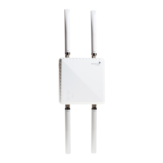
AP1130 Installation Guide
The AP1130 is a multi-channel wireless access point with a watertight chassis that can be
deployed in virtually any outdoor setting, including extreme environments.
This guide explains how to install the AP1130 on a pole or flat surface in virtually any
outdoor setting, and connect it to Aerohive HiveManager Network Management over the
network. To register, get the latest product documentation, see compliance information, and
download software updates, visit www.aerohive.com/support. For detailed hardware
information about this device, visit www.aerohive.com/quick.
FCC and IC statements can be found on page 12.
Kit Contents, Required Accessories, and Tools
The AP1130 kit includes the items shown below.
AP1130
chassis
To install your AP1130, you will need the following accessories (ordered separately) and tools:
•
Two 2.4 GHz antennas
•
Two 5 GHz antennas
•
A switch that provides PoE power, or a PoE provisioning device, a DC backup battery (requires the
DC power cable accessory, part number AH-ACC-1130-CBL-DC), or solar panel
•
A shielded cat5 Ethernet cable rated for outdoor use; length not to exceed 328 feet (100 m)
•
PoE Injector (optional).
•
Crosshead screwdriver for pan head screws and Reset button cover
•
Flat blade screwdriver to tighten the hose clamp
•
Security Torx (pin-in-Torx) screwdriver for the captive screws in the mounting bracket
P/N 330120-02, Rev. A
®
Hose clamp
Bracket (1)
Waterproof
Ethernet housing
Ground cable (1)
Four pan head wall
mount screws in the bag
labeled "WALL MOUNT"
Five pan head machine
screws with washers for
pole mount and ground in
bag labelled "POLE MOUNT &
GROUNDING"
1
Advertisement
Table of Contents

Related Manuals for Aerohive AP1130


Summary of Contents for Aerohive AP1130
- Page 1 The AP1130 is a multi-channel wireless access point with a watertight chassis that can be deployed in virtually any outdoor setting, including extreme environments. This guide explains how to install the AP1130 on a pole or flat surface in virtually any outdoor setting, and connect it to Aerohive HiveManager Network Management over the network.
-
Page 2: Hardware Components
Hole for ground Safety Instructions and Site Hazard Warnings Read and follow these safety instructions and hazard warnings before installing an AP1130. Keep these instructions for future reference. The following icons are used to identify the type of caution or warning in this document: This icon indicates a general caution. -
Page 3: Installing The Ap
Do not locate the AP1130 enclosure near overhead power lines or other electric light or power circuits, or where it can come into contact with such circuits. During installation, exercise extreme care not to come into contact with these circuits, which can cause serious injury or death. -
Page 4: Power Connections
Power Connections In most cases, you can connect an Ethernet cable directly from your AP1130 to a PoE-enabled switch, or to a PoE injector inside the building. You can also connect your AP1130 to a DC power source, such as a battery backup or solar panel. - Page 5 Vertical or Horizontal Pole Mount The following steps explain how to mount the AP1130 on a vertical or horizontal pole. The pole can be from 1.0 - 2.75 inches (25 to 70 mm) diameter. You can also order a hose strap that will fit poles with a 3" to 15" (76 to 381 mm) diameter (AH-ACC-1130-STRP-3-15).
- Page 6 Grounding lug Correct Alignment for Horizontal Mounts When attaching the AP1130 to a horizontal pole, such as the arm of a street light, make sure that the face of the device is perpendicular to the Earth for optimal RF coverage.
-
Page 7: Flat Surface Installation
Flat Surface Installation The following steps explain how to mount the AP1130 on a flat surface or wall. You will need the mounting bracket and the four bolts without washers in the plastic bag labeled “Wall Mount”. You will also need four mounting screws and wall mount anchors (not included) that are appropriate for the wall type where you are installing the unit. -
Page 8: Attaching The Ethernet Cable Waterproof Housing
In the Modify dialog box, in the section under Device Classification where you assign radio profiles, for an AP1130 you will see a field at the far right where you can select the antenna type. Make sure that omni is selected for both bands. -
Page 9: Accessing The Reset Button
Disable the antenna buzzer. AP1130 LEDs The AP1130 has a Status LED on the bottom of the unit, and a Signal Strength LED and three connectivity LEDs on the right panel. The LED colors and what they indicate are described below. -
Page 10: Connecting To The Network
PoE and Ethernet Protection In most cases, you can connect an Ethernet cable directly from the AP1130 to a PoE-enabled switch or to a PoE injector inside the building. In some cases, you might need to install an outdoor, waterproof PoE injector. - Page 11 Appliance, the redirection server automatically redirects the CAPWAP connection to that HiveManager instance by sending the AP1130 the HiveManager domain name or IP address as its new CAPWAP server. If the AP is currently using HTTP and it will be redirected to a HiveManager Online VHM, the redirection server also sends it the configuration it needs to continue using HTTP.
-
Page 12: Where To Find More Information
Aerohive also offers CBT (computer-based training) modules. CBTs are online Flash tutorials that explain Aerohive concepts and walk you through configuration procedures step by step. You can use CBTs to familiarize yourself with the HiveManager GUI and learn how to configure HiveAPs. Aerohive CBTs are available for free online at www.aerohive.com/techdocs. - Page 13 être installé et utilisé avec un minimum de 20 cm de distance entre la source de rayonnement et votre corps. This radio transmitter (AP1130) has been approved by Industry Canada to operate with the antenna types listed below with the maximum permissible gain and required antenna impedance for each antenna type indicated.
Need help?
Do you have a question about the AP1130 and is the answer not in the manual?
Questions and answers