Table of Contents
Advertisement
Quick Links
User's
Model MY40
Manual
Insulation Resistance Tester
Thank you for purchasing the Yokogawa MY40 Insulation Tester.
To optimize all the functions of the instrument, please read this manual thoroughly before operating it.
Store this manual in a safe place for future reference.
1st Edition : Nov. 2000(YG)
All Rights Reserved, Copyright ©2000, Yokogawa M&C Corporation
1. Safety Precautions
Always observe the following instructions. Failure to do so may result
in electrical shock or other dangers that may lead to serious injury or
the loss of life.
Yokogawa is in no way liable for any damage resulting from the user's
mishandling of the tester.
For safe use of this tester, the following safety symbols are used in the
user's manual:
WARNING
Indicates a hazard that may result in the loss of life or serious injury of
the user unless the described instruction is abided by.
CAUTION
Indicates a hazard that may result in an injury to the user and/or physi-
cal damage to the product or other equipment unless the described
instruction is abided by.
Note
This provides important information for handling the tester and clari-
fies tester functions.
The following symbols are used on the MY40 tester.
Danger! Handle with Care.
This symbol indicates that the operator must refer to an explanation in
the user's manual in order to avoid risk of injury or death of personnel
or damage to the tester.
High-voltage Terminal
This symbol indicates a dangerous voltage level (terminals with volt-
ages exceeding 1000 volts must be so marked). Never touch the termi-
nals.
AC Voltage
This symbol indicates the presence of an AC voltage.
Double Insulation
This symbol indicates double insulation.
3. Measuring Functions and Additional Features
Measuring Functions
• Measuring the insulation resistance (four ratings)
125 V/ 200 MΩ
250 V/ 200 MΩ
500 V/ 2000 MΩ
1000 V/ 2000 MΩ
• Measuring AC voltages (sine wave at 45 to 400 Hz)
• Measuring conductor resistances (0 to 400.0 Ω)
Continuity test (beeps for 40 Ω or less)
Additional Features
• Memory feature (data saving)
Up to 20 measured values of the insulation resistance for each
rating can be saved to memory.
• Live-line alarm
When an AC voltage of 40 V or more is applied between the
input terminals, the ALARM LED flashes and the buzzer beeps
(except during AC voltage measurement).
• Comparator
When a measured insulation resistance is less than the refer-
ence value setting, the LOW mark appears and the buzzer
beeps.
• HOLD feature
Measured insulation resistances are automatically held for
approximately five seconds.
• High-voltage indication
If a DC voltage exists between the terminals, the HV mark
and the ALARM LED come on.
• Discharge feature
The tester is designed to begin discharging when the MEAS
key is turned off.
It indicates the discharging status with a bar graph, and the
HV mark and ALARM LED come on during discharging (and
off when discharging is complete).
• Auto-power off
The tester is automatically turned off when no key operations
are performed for 10 minutes.
• LCD backlight
The backlight can be turned on/off with the LIGHT key.
• Locking the MEAS key
Pulling the MEAS key up allows for continuous measurement
over a prolonged time.
• Lock for inadvertent setting of 1000-V range
This mechanism protects the measured circuit from damage
due to inadvertent measurement with the highest voltage
(1000 V).
5. Display Functions
Lit when the measured insulation resistance is being held.
Flashes when the battery voltage is low.
Lit when the rating setting is 1000 V/2000 MΩ.
Lit when the rating setting is 500 V/2000 MΩ.
Lit when the rating setting is 250 V/200 MΩ.
Lit when the rating setting is 125 V/200 MΩ.
OL
Indicates overrange.
Indicates the extension bar graph.
The extension bar graph shows how the measured value is
changing (trend) as follows:
Note that the number of
marks means the degree of
change.
A2
IM MY40-E
6th Edition: Aug. 2008 (KP)
WARNING
Always observe the following instructions. Failure to do so may
result in electric shock or other dangers that may lead to serious
injury or the loss of life.
1. During Measurement of Insulation Resistance
• A high voltage is present at the probes. Do not touch the measured
object or the earth or line terminal.
2. Immediately After Measurement of Insulation Resistance
• The probes or the measured object may remain highly charged.
Do not touch them immediately after the completion of measurement.
3. During Measurement of AC Voltages
• Do not press the MEAS key while measuring AC voltages.
• Voltage that exceeds the specified limit must not be applied to terminals.
4. Probes
• Use the probes supplied by Yokogawa with this tester.
• Do not use probes that have deteriorated or are defective.
• Remove the probes from the measured object before attaching/
detaching the probes to/from the tester.
5. Insulation of Casing
• A puncture in the protective insulation may occur if there are any
cracks or other damage in the casing as a result of the instrument
having been dropped or knocked against another object.
Do not use the instrument before taking the necessary remedial
measures; ask the manufacturer to repair it.
6. The Measured Object
• Turn off the power to the measured object before you begin
measuring insulation resistance.
• Avoid touching any electrified parts while using the tester in
a location with live electricity. For safety, it is recommended that
you use a pair of rubber gloves or other alternative means.
7. Operating Environment
• Do not operate the tester in an atmosphere where any flammable
or explosive gas is present.
• Do not use the tester if there is condensation on it.
8. Disassembly
• No person, except personnel from Yokogawa is authorized to
disassemble this instrument.
Ontline of Measurement Principle
A/D converter
and insulation
LCD
resistance
calculation
Function (range)
circuit
selector switch
High voltage
generator
MEAS key
circuit
Discharge feature
Four AA-size batteries
Block Diagram of Insulation Resistance Measurement Circuit
4. Overrange Display Functions
OL Display
The tester displays the OL mark when the measured resistance
exceeds the following values.
Insulation resistance measurement:
For 1000 V and 500 V ratings: 2000 MΩ
For 250 V and 125 V ratings: 200 MΩ
Conductor resistance measurement: 400 Ω
∞
Display
∞
The tester displays the
mark when the internal calculation
exceeds the following values.
Insulation resistance measurement:
For 1000 V and 500 V ratings: approx. 4000 MΩ
For 250 V and 125 V ratings: approx. 400 MΩ
Change to Upper/Lower Ranges
• To upper range
When the digital reading exceeds 4000, the measuring range
changes to the next upper range.
• To lower range
When the digital reading falls below 360, the measuring range
changes to the next lower range.
Lower Resolution Display
If the digits below the decimal point are not stable, they can be
automatically omitted to limit the resolution.
: Change toward smaller values
: Change toward larger values
: Stable
Lit when:
• Pressing the MEAS key in insulation resistance measure-
ment; and
• Residual electrical charges are present during discharg-
ing.
Lit when the comparator is activated.
Lit when the measured insulation resistance is lower than
the comparator setting value.
Lit when the memory feature is in use.
Indicates the unit for AC voltage measurement.
Indicates the unit for insulation resistances.
Indicates the unit for conductor resistance measurement.
Indicates the continuity mark, which is lit when the
measured insulation resistance is lower than 40 Ω.
Sub-display
Indicates:
• Comparator setting value or the storage number; or
• The storage number for memory.
Indicates the unit for insulation resistance for comparator.
Yokogawa Meters & Instruments Corporation
International Sales Dept.
Tachihi Bld. No.2, 6-1-3, Sakaecho, Tachikawa-shi,Tokyo 190-8586 Japan
Phone: 81-42-534-1413, Facsimile: 81-42-534-1426
YOKOGAWA CORPORATION OF AMERICA (U.S.A.)
Phone: 1-800-888-6400 Facsimile: 1-770-254-0928
YOKOGAWA EUROPE B. V. (THE NETHERLANDS)
Phone: 31-33-464-1611 Facsimile: 31-33-464-1610
YOKOGAWA AMERICA DO SUL LTDA. (BRAZIL)
Phone: 55-11-5681-2400 Facsimile: 55-11-5681-4434
YOKOGAWA ENGINEERING ASIA PTE. LTD. (SINGAPORE)
Phone: 65-6241-9933 Facsimile: 65-6241-2606
YOKOGAWA MEASURING INSTRUMENTS KOREA CORPORATION (KOREA)
Phone: 82-2-551-0660 to -0664 Facsimile: 82-2-551-0665
YOKOGAWA AUSTRALIA PTY. LTD. (AUSTRALIA)
Phone: 61-2-8870-1100 Facsimile: 61-2-8870-1111
YOKOGAWA INDIA LTD. (INDIA)
Phone: 91-80-4158-6000 Facsimile: 91-80-2852-1441
YOKOGAWA SHANGHAI TRADING CO., LTD. (CHINA)
Phone: 86-21-6239-6363 Facsimile: 86-21-6880-4987
YOKOGAWA MIDDLE EAST B. S. C (C) (BAHRAIN)
Phone: 973-17-358100 Facsimile: 973-17-336100
YOKOGAWA ELECTRIC CIS LTD. (RUSSIAN FEDERATION)
Phone: 7-495-737-7868 Facsimile: 7-495-737-7869
Measurement Categories
Measurement category
Description
1
CAT.1
For measurements performed on circuits
not directly connected to MAINS.
For measurements performed on circuits
2
CAT.2
directly connected to the low voltage installation.
For measurements performed
3
CAT.3
in the building installation.
For measurements performed
4
CAT.4
at the source of the low-voltage installation.
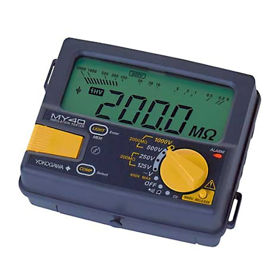
6. Functions for Each Component
1. Display window (LCD)
Displays the measured values and the function marks (see section
5, "Display Functions").
2. MEAS key
Used for measuring the insulation resistance only.
3. LIGHT key: Used for turning on/off the backlight.
LINE
(MEM key): Also used for setting memory.
(Enter key): Also used for confirmation for the comparator and
memory functions.
4. Protective cover fitting
EARTH
5. COMP key: Used for setting the comparator.
(Select key): Also used for selection for the comparator and
memory functions.
6. ALARM LED
Flashes for the live-line alarm, and is lit as a warning for the high
-voltage alarm.
7. Function switch
A rotary switch for setting measurement ratings with the following
positions:
• 1000 V/ 2000 MΩ: Insulation resistance measurement
• 500 V/ 2000 MΩ: Insulation resistance measurement
• 250 V/ 200 MΩ: Insulation resistance measurement
• 125 V/ 200 MΩ: Insulation resistance measurement
• AC voltage measurement (maximum input voltage: 600 V)
• Power off
• Conductor resistance measurement
Continuity test
CLr:
Memory clear
8. 1000-V RELEASE button
Turn the function switch to the 1000 V rating position while press-
ing this button.
9. Battery cover setscrew
Undo to replace batteries.
10. Battery cover
11. Shoulder strap guide
The shoulder strap is passed through it.
12. Earth terminal
Connection for earth probe.
13. Line terminal
Connection for line probe.
Note
• GUARD function is not a standard function.
8. Before Measurement
1. Safety
• Read the handling precautions in this manual carefully.
• Make sure it is safe before starting measurement.
2. Battery Voltage Verification
• Make sure that the battery voltages are within the valid rat-
ings (i.e. the
mark is not flashing).
• If the batteries are low, replace them as specified in the bat-
tery replacement section of this manual.
Note
As the
mark indication depends on the load (current
consumption), check that the
mark does not appear for the
largest load when short-circuiting the earth probe and the line probe
(0 MΩ).
3. Connecting the Probes
• Plug the earth probe into the earth terminal.
• Plug the line probe into the line terminal.
WARNING
• Remove the probes from the measured object before attaching/
detaching the probes to/from the tester.
• Make sure the MEAS key is off when attaching/detaching
the probes to/from the tester.
4. Function Switch Verification
Be sure to confirm that the function switch is set to the desired rat-
ing.
5. 1000-V Rating
When measuring with the 1000-V rating, see section 12, "Double-
action 1000-V Function".
About This Manual
• The contents of this manual are subject to change without prior
notice.
• Every effort has been made to ensure accuracy in the
preparation of this manual. Should any errors or omissions come
to your attention however, please inform Yokogawa Meters &
Instruments Corporation accordingly.
• Under absolutely no circumstances may the contents of this
manual be transcribed or copied, in part or in whole, without
obtaining permission.
IM3E-2008.8
2. Components
Remarks
Appliances, portable equipments, etc.
Distribution board, circuit breaker, etc.
Overhead wire, cable systems, etc.
3. LIGHT key
INSULATION
TESTER
Internal Wiring
2. MEAS key
MEAS
PULL LOCK
Distribution
CAT.
3
CAT.
2
Board
Entrance
Cable
T
CAT.
4
CAT.
1
Fixed Equipment,
Outlet
etc.
Equipment
5. COMPARATOR key
Side view
12. Earth terminal
13. Line terminal
7. Using Protection Cover and Shoulder Strap
The tester comes with a protection cover and shoulder strap as
standard accessories.
• The protection cover can be used as a front cover
(for the display window) or as a bottom cover.
(It is set as the front cover when
delivered from the factory.)
• Using the shoulder strap allows you to position the
tester in front of your chest for ease of reading. Pass
the strap through the shoulder strap guide and ad-
just the length of the strap to allow you a good view
of the tester.
• Remove the cover from the front, and attach it to
the bottom using the fixing hole (B) on the surface
of the cover. This is useful when the diaplay is too
close to your body to see clearly (See the figure
on the right).
• A belt on the cover which is fitted with pieces of
Velcro, can be used to store the probes (Remove
the probes from the tester terminals when storing
them).
Protection cover
Shoulder strap guide
9. Battery Replacement
WARNING
• Remove the probes from the tester and then turn off
the MEAS key before opening the casing to replace the batteries.
• Do not touch the MEAS key during replacement. Otherwise,
a high voltage may be produced.
1. Loosen the battery cover setscrew, and then slide the cover off of
the main unit.
2. Replace all of the 4 batteries at the same time and make sure the
polarities of the new batteries are exactly as shown on the
battery holder.
3. After replacing the batteries, attach the battery cover and tighten the
setscrew.
CAUTION
• Do not mix batteries of different types or new batteries with used ones.
• Always remove the batteries if the tester will not be used for
a prolonged period of time. If you store the tester with the batteries
left installed, fluid is likely to leak from them, resulting in
a malfunctioning of the instrument.
10. Battery Life (Reference only)
For MY40 at rated 500 V/2000 MΩ:
Approximately 15 hours when in continuous operation with center value
indicated (approx. 50 MΩ; with standard supplied batteries).
Note
The data above is typical. Nevertheless, the battery life varies
depending on the operating conditions. Check the batteries before
measurement.
Front view
1. Display window
(LCD)
1000V
ALARM
6. ALARM LED
LIGHT
Enter
2000MΩ
500V
MEM
7. Function selector switch
250V
200MΩ
125V
V
600V MAX
COMP
Select
OFF
1000V RELEASE
Clr
8. 1000-V RELEASE button
for setting 1000-V rating
4. Protective cover fitting
Rear view
11. Shoulder strap
guide
OPEN
9. Battery cover setscrew 10. Battery cover
Protection cover fixing holes
Shoulder strap
A
B
Advertisement
Table of Contents

Related Manuals for YOKOGAWA MY40


Summary of Contents for YOKOGAWA MY40
- Page 1 For measurements performed on circuits CAT.2 Appliances, portable equipments, etc. injury or the loss of life. Yokogawa is in no way liable for any damage resulting from the user's Front view directly connected to the low voltage installation. mishandling of the tester.
- Page 2 : ± (5% of rdg +12dgt) • AC Voltage measurement It is recommended that the tester be calibrated once every year for • Conductor resistance measurement : ± (10% of range) correct operation; ask Yokogawa to do the periodic calibration for you. IM MY40-E <2>...
Need help?
Do you have a question about the MY40 and is the answer not in the manual?
Questions and answers